Kangabot/Spring/2021
Time of flight vl6180x front shield breakout board
Author/s:Eric Ornelas (controls engineer)
Table of Contents
Introduction
A first time for creating a breakout board for the 3DOT can be a fun process in learning the software and assembling the board.
PCB design software
A CAD software is necessary for designing a printed circuit board or breakout board for the 3DOT board. Autodesk provides free software that is called Eagle CAD, which has enough tools to design a break out board. Eagle CAD is the software that was used to make a time of flight sensor. A link to the software is provided in the reference section of the page.
VL6180x foot print and symbol
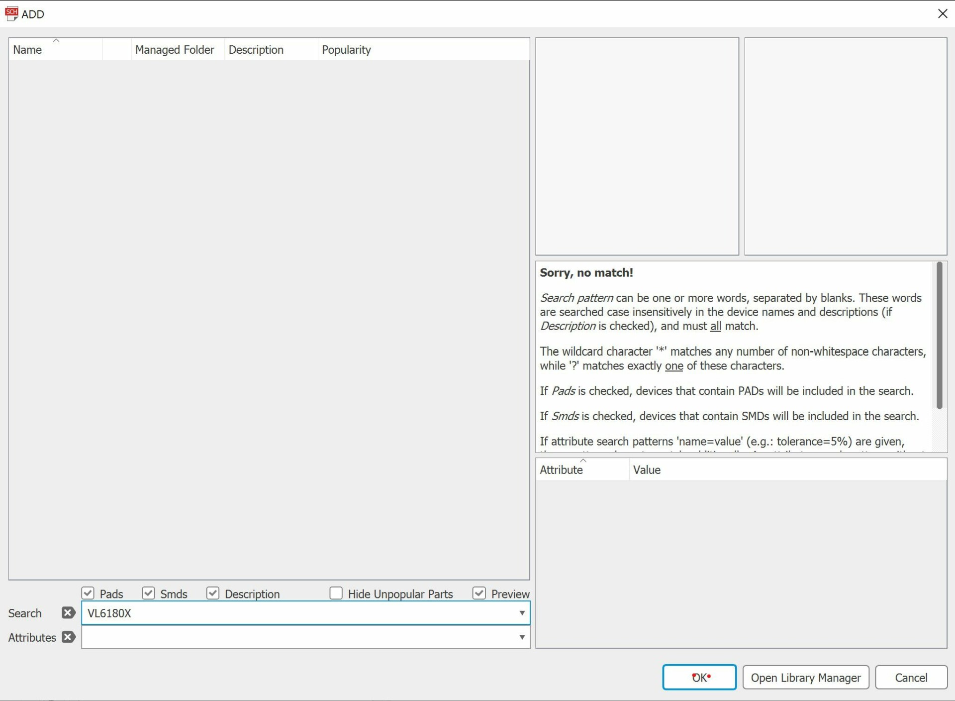
The vl6180x symbol is not included with the Eagle CAD library. Through a google search, VL6180x eagle cad library, the st-microelectronic library contains the VL6180x footprint and symbol. The link to the library is provided in the reference section of the blog post.
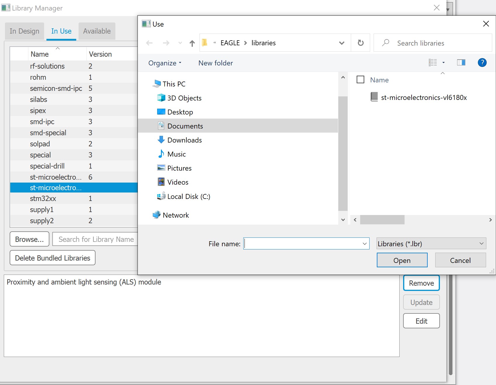
In the pc file explorer, locate the eagle cad library section and insert the st-microelectronics library. This is where eagle cad will locate the file for the vl6180x symbol.
In the schematic page of eagle cad, add the file to the library by opening the library manager, locate the browse button on the lower left hand side and open the file where the library is located.
Components and schematic
Components used in making the TOF sensor on eagle cad.
- 10k ohm pull up resistor: Pull-up resistors for the logic level shifting mosfets.
- 47 k ohm pull up resistor: Pull-up resistor which pulls the shut down pin of the vl6180 sensor high. This is necessary to keep the sensor turned on.
- MIC5225_2.8V LDO: The TOF sensor has an operational voltage between 2.7- 2.9 volts. A 2.8V low-dropout voltage regulator is needed to step down the 3DOT’s 3.3 Voltage to 2.8 voltage.
- 10uf capacitor: Used for the LDO voltage regulator.
- 0.1 uf capacitor: Used for the vl6180x sensor.
- Mosfet Bss138- Used for the logic level shifting of the I2C SDA, and SDL pins.
- VL6180x- Time of flight sensor.
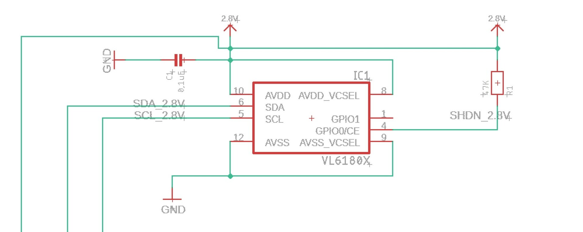
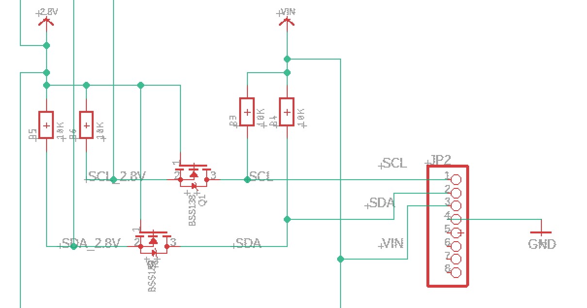
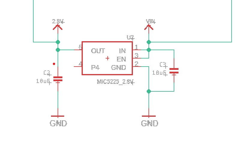
- Naming the connections are necessary because it will make it easier when connecting the traces in the board page.
Board
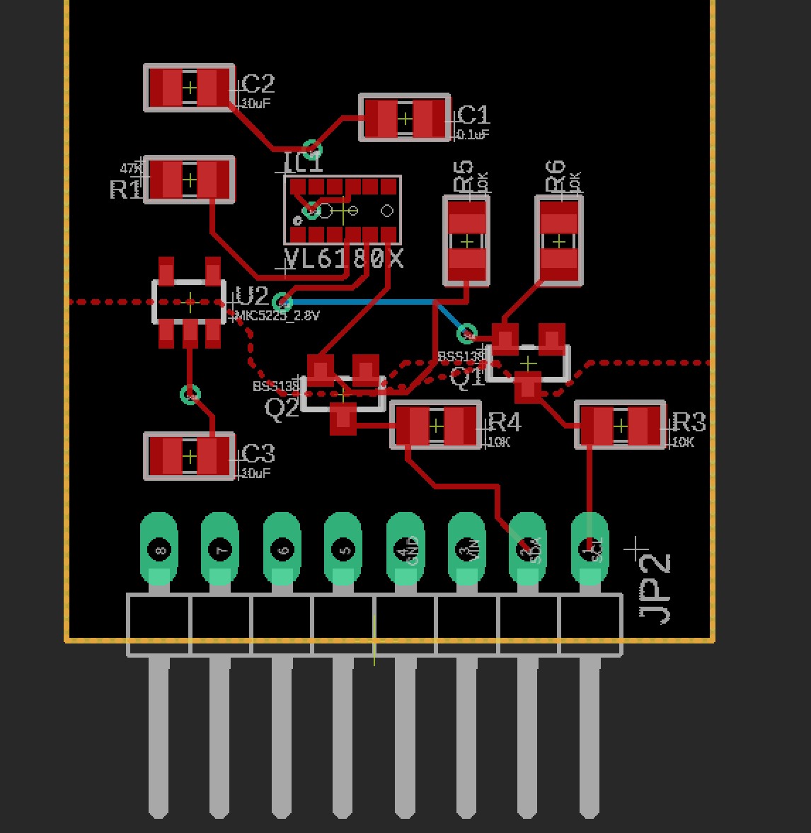
The assembled board on autocad. A gerber file can be made by selecting the top right file dropdown menu and clicking on create cam data. Gerber file is needed when you want a manufacturer to produce your board.
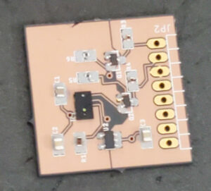
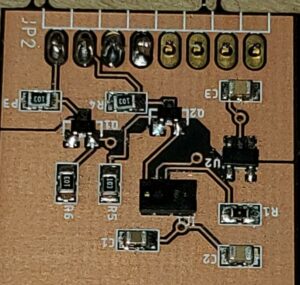
Finished production of the breakout board. Solder paste and a stencil was used for applying the paste on the breakout board. An electric skillet was used to heat the board in which melts the solder paste and solders the components onto the breakout board. Solder paste is toxic, so wear plastic gloves when handling solder paste and clean or throw away items with solder paste.
Conclusion
The breakout board was designed to be fitted on the front shield pins of the 3DOT board. The project showed how a printed circuit board is designed on eagle cad and how to get it manufactured through a manufacturer online.

