Design(s) of 3D printed attachments Spring 2016
Posted by: Luis Valdivia (Project Manager)
Written by: Juan Mendez (Manufacturing Engineer)
Our vehicle has a yaw problem which causes it to be unstable. After brainstorming a few ideas, we have decided to attack this problem by adding on attachments in order to perform thrust vector control using servos and also be adding flaps to redirect the direction of the thrust.
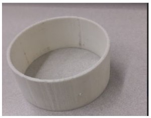
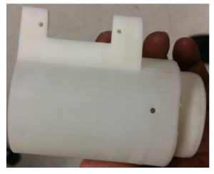
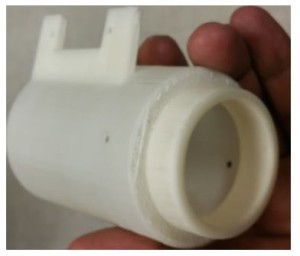
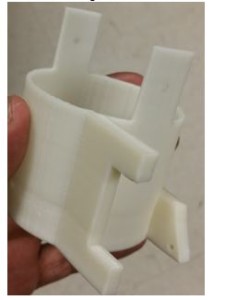
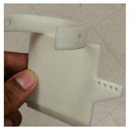
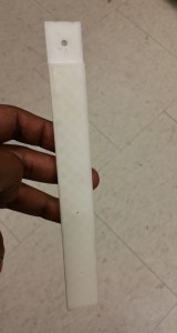
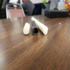
Before making our design, there were several parameters that we had to take into account such as ensuring that the attachments fit the ducted fans. For one we needed to keep the attachments as light as possible to not add on too much weight on to the vehicle however we could not for too light for several reasons. The parts that were 3D printed needed to be no less than 2 mm thick. The reason for this is because the 3D printer that we were using could not print any less than that. We first had a prototype printed to see if we could use a 3D printed part that was the thin. Once we had printed it, we saw that the part was way too thin to use and was easily broken. In order to make sure that the attachments weren’t too thin to break, we increased the thickness to 2.54mm which is roughly .1 inches thick. Once we printed a small prototype, we saw that it was much more durable than the 2mm one and we were able to easily drill through it without breaking as seen in Figure 1.
Figure 1 3D printed duct attachment
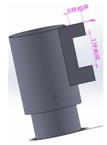
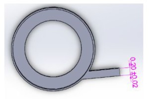
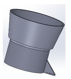
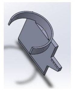
The next minor challenge that I had to consider was being able to mount on servos to the attachments. The servos were measured to have a height of 1.18 inches and needed to be mounted on to the cylindrical shape. We were initially going to make brackets and screw them in to lock the servos in place however it would be a challenge since we did not have a flat surface and we did not know if adding on screws into the attachment would affect the air flow. After consulting with my project manager, he suggested extruding a thin block out of the attachments and then mounting them onto their. I went with this suggestion and properly dimensioned the extrusion to fit the servo. Initially I designed the extrusion block to be roughly 1x .2x 2.25 inches in size. From there I made an inner cut that was .53x 1.19 inches so the servo can easily fit in (Figure 2). I had these printed and checked to see if both servo EDF could fit on to the attachment. Sure enough both did. In order to secure the servo, I had to drill into the extruded block. For this reason I made the block .2 inches thick, so it would not break off when drilling (Figure 3). Once making the holes, the servo was easily mounted on to the attachments.
Figure 2 CAD of thrust vector chamber with servo flaps (side view)
Figure 3 CAD of thrust vector chamber with servo flaps (top view)
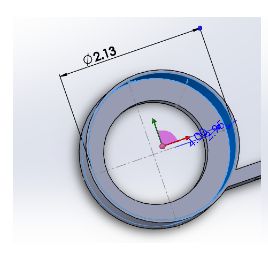
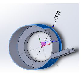
Next we had to make sure that these attachments fit into our Electric Ducted fans. The ducted fans that we were using have an outer diameter of 53mm. I dimensioned the attachments to be slightly bigger than this in order for it to be able to slip on to the EDF. In order to not waste material and time, I had only one attachment be printed. Sure enough it did not fit and was way too tight to even slip on without damaging the attachment. I made designed the attachments to have roughly an inner diameter of 54.1mm which was approximately 2.13 inches (Figure 4) with an outer diameter of 2.23mm (Figure 5). Once making the adjustments, we were able to slip on the prototype into the EDF.
Figure 4 CAD of thrust vector chamber demonstrating inner diameter
Figure 5 CAD of thrust vector chamber demonstrating outer diameter
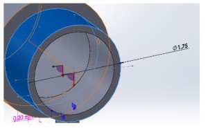
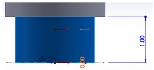
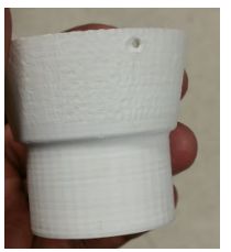
Since we were going into thrust vectoring, I needed to make sure that the servos could move the attachments without causing any problems. One of the issues I noticed when designing the attachments was that after it rotating roughly 45 degrees, there was going to be a gap that would make air leak out, which could cause an addition issue when trying to stabilize the vehicle. To fix this problem, I made an inner cylinder to close off the gap and made it to have an outer diameter of 1.75 inches (Figure 6) and a length of 1 inch (Figure 7). Because of this, when the middle attachment rotated, there was no gap to leak air. The fabricated part can be shown in Figure 8A & B.
Figure 6 CAD of thrust vector chamber demonstrating inner diameter (second level)
Figure 7 CAD of thrust vector chamber demonstrating outer diameter (second level)
Figure 8A 3D Printed thrust vector chamber (side view)
Figure 8B 3D Printed thrust vector chamber (alternate view)
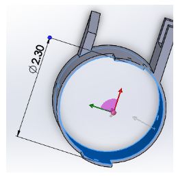
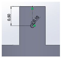
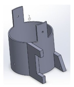
Next was to design the middle attachment. The middle attachment was a much simpler design since much was learned from making the top one. This one just needed to have an inner diameter that was slightly bigger than the top one so it can fit and move. In order to give it a bit more space to move, this attachment had in inner diameter of 2.3 inches (Figure 9). In order to mount on this attachment to the top one, I made the mounts to be roughly 1 inch tall to compensate for the inch clearance that was given from the top attachment. I made a pilot hole on this that is in the center of the mount which was roughly .5 inches from the top of the attachment (Figure 10). An extrude block was added on to this attachment as the previous one, however an additional extrude block was added on in the back in order to have the servo joint attached on to it (Figure 11). There, the top servo was going to push and pull on to this attachment. Ideally this part was not meant to be this long, however we needed to give enough space for the servo. To control the bottom attachment. The fabricated part can be shown in Figure 12.
Figure 9 CAD of thrust vector chamber demonstrating inner diameter
Figure 10 CAD of thrust vector chamber attachments
Figure 11 CAD of thrust vector chamber (second level)
Figure 12 3D Printed thrust vector chamber
Lastly we needed to make the bottom attachment. This was the simplest design since it was a funnel shape. In height, the funnel ended up being roughly two inches. As before, an extruded block was added on to this but just to connect to the servo, not to mount on (Figure 13). The fabricated part can be shown in Figure 14.
Figure 13 CAD of thrust vector chamber (lowest level)
Figure 14 3D printed thrust vector chamber (lowest level)
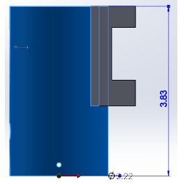
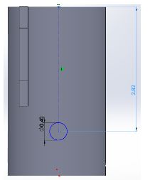
Our second design was to control the yaw by adding flaps to counter the direction of the thrust. For this design, the top part was relatively similar to the previous one except it this not have an additional cylinder to close off any air gap. Also the height was made slightly smaller for the same reason of not having to worry about the air gap. The height of this attachment was roughly 3.83 inches with the same thickness and diameters of the previous design (Figure 15). The reason for this height again was because the EDF height including the coils was roughly 2.82 inches so I needed to make sure that there was a hole big enough to fit in the wires to power it on (Figure 16). In order to make this hole big enough, I needed to make sure there was enough space to make it. Also I needed to make sure that the flaps had enough space to mount on to the attachment.
Figure 15 CAD of thrust vector chamber demonstrating dimensions
Figure 16 CAD of thrust vector chamber with inner diameter
There was much thought put into making the flaps to control the direction of the thrust. Initially the idea was to have the flaps go inside and the servo would rotate it however the problem with this was that it could not go in the middle of the attachment. The reason for this is because as the flap turned, there would be a big gap which would leak air out in a direction which would not be in our control. To attempt to solve this, we thought of making the top part of the flap bigger to block off the air gap. The problem with is now was that the top part was going to easily hit the attachment and would not let the flap rotate the way it should. The third idea was had was to remove the flap from being in the middle and putting it in the inner corner of the attachment. This did not work simply because the flap would not be able to rotate without hitting the attachment. After thinking it over with the project manager, we decided to mount on the flap outside of the attachment. I designed the flap to be able to mount on to the cylindrical attachment by making it the same shape. Some parts were trimmed off in order for it to not scrape when moving. The flap itself was designed as a prototype. It was made wide enough to cover the thrust of the EDF and long enough to redirect the thrust. The flap was made .2 inches thick in order to make it durable and hard to break as the EDF was going to be pushing against it. Similarly to the previous designs, and extruded part was added on simply to be able to attach the servo joint to push and pull the flap. The model and fabricated part can be seen in Figure 17A & B.
Figure 17A CAD of thrust vector flap
Figure 17B 3D printed thrust vector flap
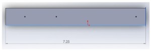
Lastly we noticed that if we were going to use all these attachments then we were going to have a problem with the legs since the attachments were long and were going to hit the floor. I modeled out new legs which were long enough so the attachments wouldn’t hit the ground when standing. These legs were approximately 7.25 inches long total but was given one inch clearance to mount them on to the vehicle (Figure 18). They were designed to be .2 inches thick so they would not break easily since it was supporting the weight of the vehicle. The fabricated part can be seen in Figure 19.
Figure 19 CAD of replacement legs
Figure 19 3D printed replacement leg
Though these attachments have been modeled and fabricated, we were not able to use any of them nor the servos simply because the added too much weight to the vehicle and made it too heavy to fly. Even adding on the servos alone made the vehicle too have so we could not use those however these concepts can be used for future semesters if they choose to go with a similar approach and taking account the weight ahead of time.

