Paperbot(DeRobot)/Spring/2021
How I Broke and Fixed my RGB Sensor Shield
Author/s: Jorge Mendoza
Table of Contents
Introduction
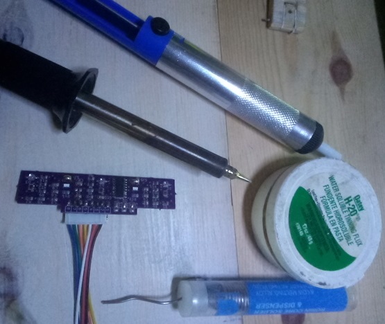
The header on my hardware was on the wrong side for mounting on to the 3Dot board header. I relocated the header to the other side of the front shield. After several simulations, I found that the header pins were too long and the sensors’ distance to the floor was too close. A new requirement was born, and I had to remove the header again to trim pins and make necessary adjustments. Normally, I would’ve bought a new header, but there was no time to wait and this is where my story begins.
Diagnostics
At the first and second time of soldering, the hardware pads at the header junction did well in staying intact. On the third time, their was doubt once completing the repair so I performed a wiggle test on the soldered pins which appeared to be holding the pin firmly.
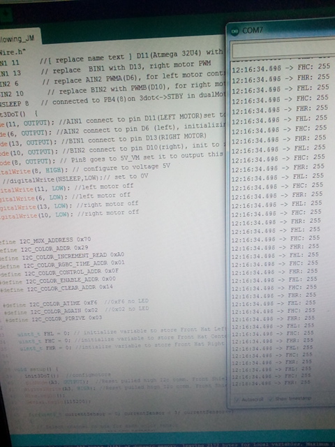
Afterwards with hardware fitted to robot, I ran my serial monitor test, and found to be getting a maximum 255 sensor value readings which was not expected. Previous testing of software revealed that this was typical characteristics when there was no I2C communications between the hardware and the 3Dot board.
Test 1: Serial Monitor test of sensor readings with 3Dot and project designed front shield. Fail. -> Test 2
Test 2: Digital Multi-Meter readings at 3Dot header: SDA~3.0 SCL~3.0, GND test to USB Ground, 3.3V=3.3V, A3=3V(Software). OK. -> Test 3
If there wasn’t power and grounds we would investigate further at this point back to the battery and ground circuit of 3Dot.
Test3: Serial Monitor test with Arduino Uno taking sensor readings of front shield. Fail.
If the sensor values were okay with Uno, we would investigate back at the 3Dot, but the failure is still present so we look further into the hardware.
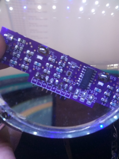
I suspected the SDA pin at the header union may be of concern due that the pad had lifted off during soldering. I consulted with my project manager and had a discussion of my findings which led to performing a continuity test between the header pin 7 and IC pin 15, on SDA. Additionally, I tested the SCL circuit right next to it. An open circuit existed between the SDA header and IC(SDA) on hardware which can be seen with red arrows in image. The green arrow is pointing at where the open circuit is which is where the pin makes contact with circuit.
Repair
The repair was to run a wire between the IC and header pin, alternatively I found a via close to the pin that connected the circuit. A bridge was created from this point to the pin.
Verification
I validated the repair by running a continuity test from the IC pin 15 and header pin 7, which an audible chirp from my multi-meter gave the Pass signal. Then I fitted hardware and proceeded to simulate my board and sensor value readings were no longer stagnant at max value.
Conclusion
Any diagnostic strategy; by hardware, or software are useful in saving time. This repair led me to consider that when designing a printed circuit board build and quality does matter. Also, the value of an LED for confirmation, instead in my case I had multiple diagnostics tools at my disposal. Their was preventive measures that could’ve avoided the situation, but the constraint was time. Technical assistance from my instructors and peers helped arrive to a quick resolution.


