Digital Slip Differential Voltage Ratio
By: Jose Alcantar, Electronics and Controls Engineer
Speed Ratio Calculation for slip differential
Purpose:
To implement slip differential turning, the speed ratio for the left and right set of wheels needs to be calculated. Further testing needs to be done to find a comfortable speed for the left and right wheels.
Procedure:
To determine the speed ratio, the distance each wheel travels was calculated. This ratio can then be applied to both the speed and the voltage applied to the motors,
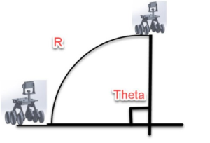
R*θ is a way of working out how far a wheel travels on a circular path. An arc with 180° gives you a θ of π radians. For example, an arc with a radius of 40 inches, the total distance the pathfinder will travel on that arc is π * 40, or roughly 125 inches. But if the center of the pathfinder is on the arc, then each wheel will travel a different arc – one outside, one inside. The wheels on the pathfinder are about 18 inches apart, so each wheel is 9 inches from the center. One wheel is on an arc of 31 inches’ radius and the other is on an arc of 49 inches (40 +/- 9). The inside wheel will travel about 97 inches and the outside wheel will travel 153 inches. The ratio between the two distance will be 150:100 (rounding), or 1: 0.67, will always give you that arc. Regardless of speed if one wheel moves 1 inch at the same time the other moves 0.67 inches. Using this ratio, the arc will be given at any speed or voltage applied to the wheels.

