DragonBot/Spring/2021
Self-Balancing Robot Part 2
Author/s: Amha
Table of Contents
Introduction
The 3Dot robot comes with two wheels and a caster (to keep it balanced). Without the caster, either the front or back frame will touch the ground. In order to keep the robot balanced on two wheels without the caster, it needs a mechanism to detect the tilt and move in the direction to which it is tilting to balance itself. The information about the tilt can be obtained from the Inertia Measurement Unit (IMU). In this experiment, MPU 9250 sensor is used to sense the tilt angle.
PARTS
- MPU 9250 breakout board
- UNO R3
- DC motors
- Dual Motor Driver
- Jumper Wires
- 3DoTBot
Testing Library Files
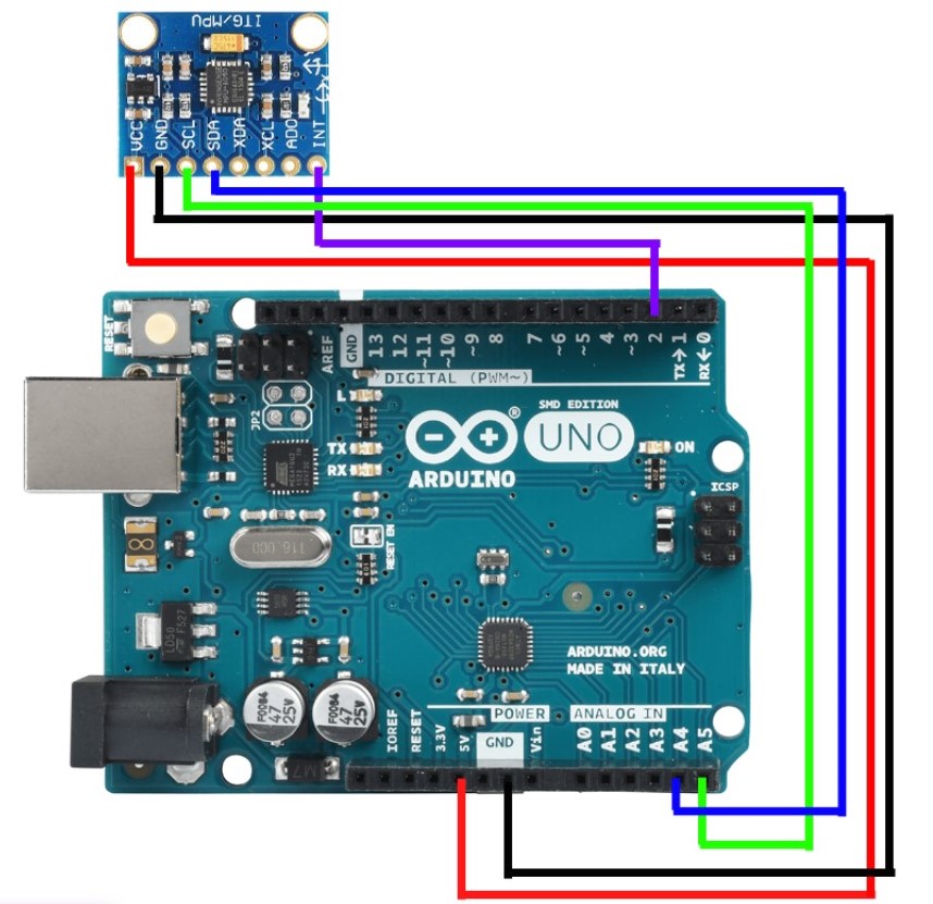
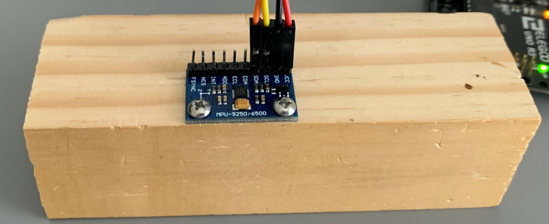
There are many Arduino library files for MPU 9250. After exploring several of the available library files for the sensor, I decided to use “MPU9250_WE.h” library file because it provides the orientation in degrees which makes it easy to work without going through the process of converting the raw data. In order to get an accurate reading, the sensor needed to be on stable surface. I mounted the sensor on a block of wood; that way, I can easily maneuver the sensor and observe the changes. The MPU9250 breakout board was connected to Arduino Uno board, as shown in the diagram below:
The sensor was moved in all 6 directions (up/down, front/back and side to side) and rotated clockwise and counter clockwise along the 3 axes (x, y and z) to observe the changes.
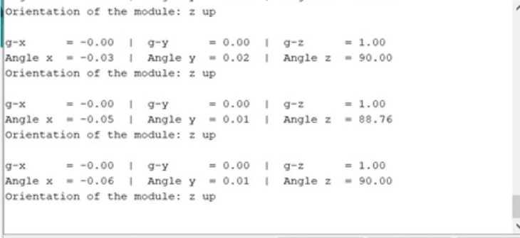
For this experiment, the front is determined to be +x direction and the upward is +z direction. When the block is at level (at rest), x-axis and y-axis are zero and z-axis is 90 degrees. On the serial monitor, it was observed that when the sensor is tilted forward tilted and/or suddenly moved, the reading from the x-axis is negative and when tilted backward tilted and/or suddenly moved it becomes positive; in contrary, the z-axis does not change a sign but the reading on the z-axis decreases to less than 90 degrees when tilting forward or backward. To determine the direction of the tilt angle, combining acceleration values along x and z axes are needed. The tilt angle (accAngle) is determined by atan2 (x, z) function.
It was noted that the gyroscope reading changes when there is a sudden tilt about the respective axis. To get a better measurement of the changes in the angle, it is important to combine the measurements of the angle from the accelerometer and gyroscope by using a complementary filter as shown in the equation below:
Angle = (1-α)*(previousAngle + gyroAngle) + α (accAngle)
PID Control
I tried to control the motor speed directly with the value proportional to the error with no success. Then, after further research, I learned that a better motor control can be achieved with a PID controller.
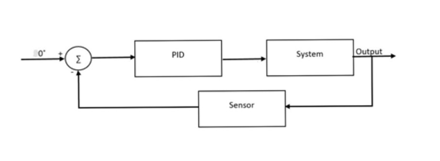
The PID controller looks at the set-point (which is 0 degrees) and compares it with the actual value of the tilt angle. If there is an error (tilt angle >0 or < 0), a corrective action is needed; this is obtained by detecting the tilt angle and moving in the direction in which it is tilting/falling.
The PID algorithm has three parts – Proportional, Integral and Derivative. The proportional term depends only on the difference between the set point and the error. The integral component sums up the error over time, and the derivative response is proportional to the rate of changes of the error.
[caption id="attachment_167647" align="alignnone" width="722"]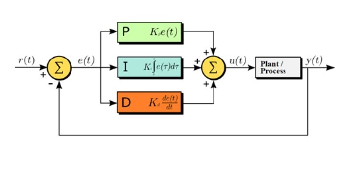 Figure 5.PID Control Schematic (courtesy to Arturo Urquizo – http://commons.wikimedia.org/wiki/File:PID.svg)[/caption]
PID Tuning
The manual tuning of PID controller requires trial and error. First, I set the KI and KD to zero, and gradually increased the KP until the robot start to oscillate – if the proportional gain is too little the robot will fall, and if the KP is too large it makes the robot oscillate wildly; a good enough KP makes the robot oscillate a little. Once the KP is set, I adjusted the KI to reduce the oscillation, then I adjusted the KD to improve the response time. The tuning process required multiple iteration (trial and error) to fine tune each parameter to achieve better result
Testing the Code
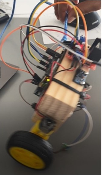
I was testing the code on a robot made from a block of wood (figure 6). Since the wires were exposed, after each test (with every fall) some pins were bent and/or broken. Therefore, I built a larger robot to enclose the wires and the Arduino board inside and continued to test the code.
After many trials and errors, I was able to balance the robot that I built. Then, I implemented the code on the 3DotBot with some modifications. I followed similar steps to tune the PID control in order to balance the 3DotBot on two wheels (video links below).
Tuning
https://drive.google.com/file/d/1qtV_QQ-OzbJ-PyP0nqiuWeA9IwatQ6SQ/view?usp=sharing
Balanced bot
https://drive.google.com/file/d/1gonyImQI58DKREKWaT1KThv-L2DVI4aB/view?usp=sharing
3Dot balanced on two wheels
https://drive.google.com/file/d/1j_6ZAPeGJM8BEQXy1Oq-RjA-BcDDdJLd/view?usp=sharing
Conclusion
To keep a robot balanced on two wheels, it needs a device to detect the tilt and move in the direction to which it is tilting to balance itself. The information about the tilt can be obtained from the sensor. The motor can be better controlled by PID controller. The PID tuning requires a lot of trial and error; the values of the PID constants are not the only unique solutions to a given robot. Furthermore, the PID constants that work for one robot may not work for another; the values of the PID controller constantans that were used for the large robot were different from the constants used for 3DotBot. It is better to test a self-balancing robot where the pins and wires are enclosed (protected/covered); exposed pins and wires get damaged during the testing process. The clearance of the 3DotBot from the ground and the extend chassis beyond the wheels made it challenging to keep the frame off the ground.

