DragonBot/Spring/2021
DragonBot: Self-Balancing Robot Part 1
Author/s: Amha
Table of Contents
Introduction
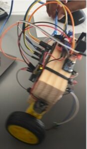
I tested the code for self-balancing robot using a robot built from a wooden block (figure 1 below) for stability. The challenge with the wooden block was that the pins and wires were exposed, and every time the robot falls, the pins were bent or broken. For that reason, I decided to build a robot that enclosed the wires and has a large clearance from the ground.
PARTS
- Two DC motors (100:1 Micro Metal Gear motor LP 6V)
- Arduino UNO R3
- DRV8833 Dual Motor Drive
-
MPU 9250 breakout board
-
Wheel 90 x 10 mm
-
Plywood 3mm thickness
-
9 volt Battery
-
Sticky back fastener (Velcro)
-
Screw with nut
-
Double sided mounting stickers
MegaBot illustration
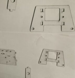
Instead of designing a new frame, I used the design of the 3Dot frame to build a larger robot. I didn’t have access to a 3D printer, therefore I photocopied the original 3Dot frames and increased the scale by 180% to use as a template to make the MegaBot. I enlarged the original frame so that the two DC motors could fit side by side (figure 2) along with the Arduino Uno R3 board.
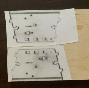
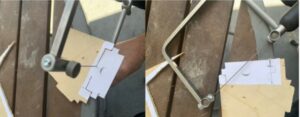
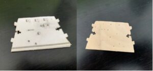
The traces (enlarged photocopies) were glued on the plywood and let dry. Since some of the designs have interior shapes that need to be cut, I drilled holes for the saw blade to fit through and I used a jeweler’s saw to cut the plywood (figure 4, 5 and 6).
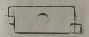
After cutting out the enlarged 3DotBot frames, the MegaBot needed an additional frame to mount the 9 volt battery. I modified the shape of the top frame of the 3DotBot as shown in the figure below (figure 7), to mount the battery at the bottom of the robot. The change was made so that the frame is not connected directly under the shaft of the motor. Then, the battery was attached to the bottom of the MegaBot by fastener (Velcro) to easily change the battery as needed.
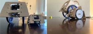
Once all the frames were cut out and the rough edges were smoothed with flies, I attached the motor driver at the center of the inside wall with a double sided sticker then attached the Arduino UNO with fastener sticker (Velcro) inside the top frame. The motors were mounted on each side of the frames and the senor was mounted on the frame above. Finally, I assembled the frame in a similar manner as the 3Dot board is assembled. The final product is shown below next to the 3DotBot.
Conclusion
Overall building the MegaBot was interesting and I was able to perform the tests for balancing successfully. Building the MegaBot which encloses the pins and wires, helped me to move forward with testing much sooner.

