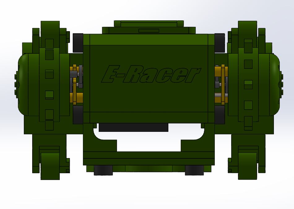
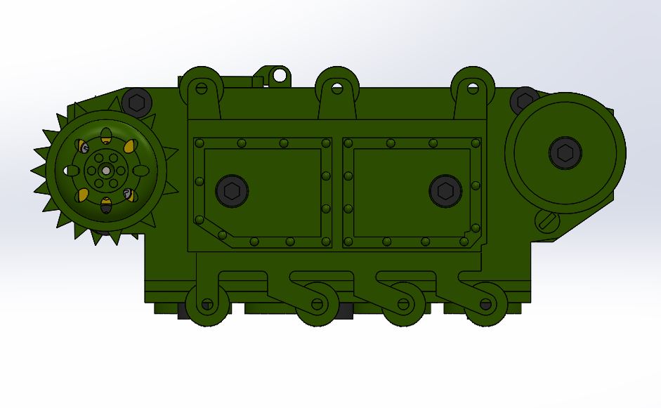
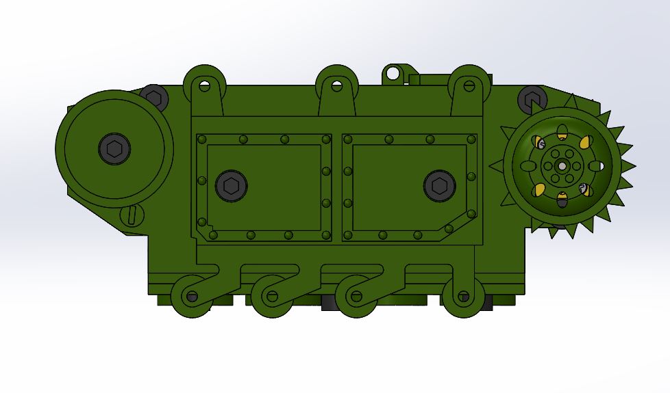
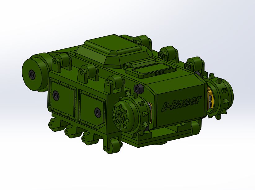
E-Racer Summary Blog Post
Author/s: Jennie Lim (Project Manager)
Jeremy Anderson (Mission, Systems, & Test)
Brandon Pantoja (Manufacturer Design)
Lundao Gao (Electronics & Control)
Table of Contents
Executive Summary
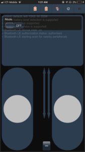
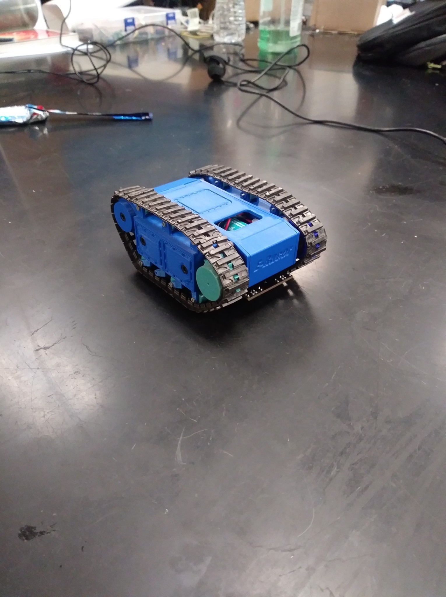
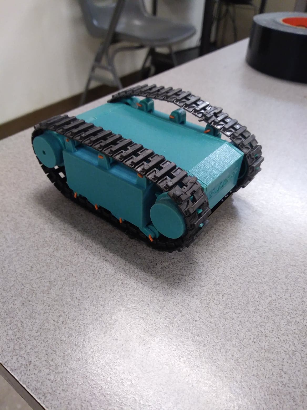
The E-Racer robot is a scale model toy of the 302 Goliath tracked mine. Its compact design includes the Arxterra 3DoT board, micro gear motors, and an IR shield. Assembly is easy for children ages 7+, they only need to plug in the motors and IR shield to the 3DoT, slide it into the chassis, and it’s ready to play. It can be controlled via the Arxterra Mission Control Panel and/or ArxRobot application. There are two play modes: autonomous line following and manual control. It could run on a vertical whiteboard surface or flat horizontal surfaces.
Program and Project Objectives
Program Objectives
The Robot Company (TRC) will be debuting its 2019 line-up of toy robots and associated games at the Toy-Invasion 2019 convention in Burbank CA on May 14, 2019. Your team’s assignment is to make the 3D printed and/or laser-cut prototypes to be showcased at the convention, prior to production starting in the second quarter of 2019. The robots will feature our new ArxRobot smart phone application and the Arxterra internet applications allowing children to interact and play games around the world. In addition, the robots should be able operate autonomously in game mode. See game(s) (i.e, mission objectives) assigned to your robot by the Game Division. To decrease electronics cost, interoperability between all TRC robots will be maintained by incorporation of the 3DoT board, developed by our Electronics R&D Section. Modification of downloadable content is limited to software switch setting and robot unique graphics of the smart phone and Arxterra applications. Modifications of electronics are limited to custom 3DoT shields as required by the unique project objectives of your robot. The Marketing Division has set our target demographic as children between the ages of 7 and 13, with a median (target) age of 11. To decrease production costs, please keep robots as small as possible, consistent with our other objectives. As with all our products, all safety, environmental, and other applicable standards shall be met. Remember, all children, including the disabled, are our most important stakeholders. Our Manufacturing Division has also asked me to remind you that Manufacturability and Repairability best practices must be followed.
Project Objectives
The E-Racer project takes the Goliath tank to new heights by giving it the ability to climb whiteboard using neodymium magnets. This generation’s design brings the toy much closer to the real Goliath in terms of scaling and is much smaller than previous generations. It is integrated with the 3DoT board which makes it easy for young kids to set up and play with. It allows them to easily customize the robot and play with it through the Arxterra app or anywhere around the world through the Arxterra control panel.
Mission Profile
The goal of E-Racer is to improve on the Goliath 302 tank design from previous generations. The mission is to autonomously complete a figure 8 course drawn on the whiteboard on the wall. It should also be able to navigate on the floor though remote control via the Arxterra App or control panel while providing a first person POV.
Project Features
- Drives vertical whiteboard surfaces and horizontal surfaces
- Reduced size compared to past models
- Ability to switch between autonomous line following or Bluetooth remote control via Arxterra App
- Implements a 3Dot Base
- Immediate access to 3DoT
- Hollow Sprockets (Drive Wheel)
- Low friction idler wheel (bearing implementation)
- Tensioner System
Requirements
Level 1 Requirements that are quantitative, verifiable, and realizable. They are created with the customer’s expectations in mind. This allows us to move the design process forward and obtain a clear understanding of what we are trying to accomplish. Level 2 requirements are design solutions the help specify how and how well the robot will perform the functions stated in the level 1 requirements.
Engineering Standards and Constraints
We are in compliance with constraints on the project imposed by The Robot Company (i.e., CSULB) and Project Stakeholders. Specifically, we include University and applicable environmental, health, and safety standards and those safety standards specifically associated with the product (e.g., Children’s Toys).
Applicable Engineering Standards
- IEEE 29148-2018 – ISO/IEC/IEEE Approved Draft International Standard – Systems and Software Engineering — Life Cycle Processes –Requirements Engineering.
- NASA/SP-2007-6105 Rev1 – Systems Engineering Handbook
- Bluetooth Special Interest Group (SIG) Standard (supersedes IEEE 802.15.1)
- C++ standard (ISO/IEC 14882:1998)
- Federal Communications Commission (FCC) Relevant standards for a product implementing a 2.4GHz radio, FCC Intentional Radiators (Radio) Part 15C, and Unintentional Radiators FCC Part 15B for CPU, memories etc.
- NXP Semiconductor, UM10204, I2C-bus specification and user manual.
- ATmega16U4/ATmega32U4, 8-bit Microcontroller with 16/32K bytes of ISP Flash and USB Controller datasheet section datasheet, Section 18, USART.
- USB 2.0 Specification released on April 27, 2000, usb_20_20180904.zip
- Motorola’s SPI Block Guide V03.06
Environmental, Health, and Safety (EH&S) Standards
CSULB College of Engineering (COE) Safety Resources. Start your search for applicable CSULB COE Safety Standards and Procedures here. Please review and acknowledge if any safety issues as defined by the COE applicable to your project. For example, the closest safety constraint for a linear actuator is for use of the Hydraulic Press located in the Engineering Technology (ET) Building Lab. Here is a link to the Hydraulic Press Safetydocument.
CSULB Environmental Health & Safety (EH&S)
IEEE National Electrical Safety Code (NESC)
NCEES Fundamental Handbook (FE) Reference Handbook
ASTM F963-17, The Standard Consumer Safety Specification for Toy Safety, is a comprehensive standard addressing numerous hazards that have been identified with toys. In 2008, the Consumer Product Safety Improvement Act of 2008 (CPSIA) mandated that the voluntary toy safety standard in effect at that time become a nationwide mandatory children’s product safety rule.
Program Level 1 Requirements
Project/Economic
Subcategories: Cost, Extensibility, Interoperability, Maintainability, Quality, Marketability, and Schedule
L1.10 All 3DoT robots shall be constrained not to exceed Cost of $250.
L1.11 All project Schedules shall be constrained to a completion date of Tuesday, May 14, 2019. Project completion includes documentation and materials purchased by or loaned to the project.
L1.12 One of the Economic Factors affecting our robots is return rates. To demonstrate the durability and child-friendliness of our robot a simple drop test from 1.4 meters should be performed. The height is defined by the average height of an average 11-year-old girl.
L1.13 Maintainability: Disassemble and Reassemble of the robot shall be constrained to less than 20 minutes (10 + 10 minutes). Disassembly: The 3Dot board is clear of all other electronic and mechanical subassemblies. All electronic and mechanical subassemblies and associated connectors, sensors, and actuators including motors are disconnected. A functional test of the robot is conducted after reassembly to confirm its functionality. All project may reference a cable tree as well as an assembly diagram as necessary. This requirement is demonstrated/verified on the last day of the schedule. Projects may request a waiver with justification.
Social and Ethical
Subcategories: Accessibility, Aesthetics, and Usability
L1.14 Accessibility by the blind and Marketability of the robots should be implemented/enhanced by a speaker. The speaker shall generate a sound effect consistent with the type of the robot. For example, the Goliath tank would make “track” sounds, the AT-ST sound effects would mimic their Star Wars antecedent.
L1.15 Wiring Aesthetics shall be nice and clean with the usage of terminal blocks, 100 mil contact pins and headers, 2.0mm PH series JST connectors, and barrel connectors. Handling Precaution for Terminal and Connector will be in compliance with JST documentation.
L1.16 To enhance Aesthetics, the robot shall be designed in such a way that there are no dangling or exposed wires. Connectors will be used between all electronic and electromechanical components. Jumper wires will not be used, ribbon cables are preferred.
L1.17 To enhance Aesthetics, the form factor of a robot modeled on a real or fictitious robot shall be constrained by the original. Goliath should be a scale model of the real Goliath 302 tank.
Manufacturability
Subcategories: Constructability, Size, Weight, and Power (SWAP)
L1.18 Manufacturability of all 3D prints provided by the library’s Innovation Space should minimize the number of files to be printed. Justification should be provided if more than one (1) file is required
L1.19 The Size of the electronics enclosure shall be constrained to be no greater than the 3DoT board, 3DoT shield(s), and associated mounting hardware.
L1.20 Power to all 3D robots shall be provided by the 3.7V RCR123A battery included with the 3DoT board or use of the external battery 2.0mm PH series JST connector located on the 3DoT board. The RCR123A is a Lithium Polymer LiPo battery. All Safety regulations as defined in Section 4.3 Hazards and Failure Analysis of this document shall apply to the shipping, handling, storage, and disposal of LiPo batteries.
Functional
L1.21 All 3DoT robots shall incorporate the 3DoT v8 or v9 series of boards.
L1.22 Software shall be written in the Arduino De facto Standard scripting language and/or using the GCC C++ programming language, which is implements the ISO C++ standard (ISO/IEC 14882:1998) published in 1998, and the 2011 and 2014 revisions. Required exceptions to this standard can be found here.
L1.23 All 3DoT robots shall be in compliance with the 3DoT Command and Telemetry Packet specification.
Project Level 1 Functional Requirements
Project level 1 requirements define the general tasks that the robot should perform to achieve its objective.
L1.1 The E-Racer will drive on horizontal surfaces made of linoleum(classroom floor).
L1.2 The E-Racer will not fall off of the intended vertical surface (whiteboard) from any orientation.
L1.3 The E-Racer shall be able to follow a course drawn on the 12’x5’ whiteboard in a classroom.
L1.4 The E-Racer will contain a custom designed PCB for a specified purpose (i.e sensor shield).
L1.5 The course shall be drawn at least the E-Racer’s width, 54mm away from the edge of the board to avoid E-Racer edge collision. (Given by customer)
L1.6 The E-Racer mobile application shall have two modes: autonomous and manual
control.
L1.7 The E-Racer shall begin moving forward anywhere within the defined start-finish area on the whiteboard.
L1.8 The E-Racer shall be smaller than the previous generation 115mm x 85mm x 44 mm.
(Given by customer)
L1.9 The E-Racer shall implement a live camera feed in first person POV.
System/Subsystem/Specifications Level 2 Requirements
The level 2 requirements provide design solutions to achieve level 1 requirements.
L2.2.1 The E-Racer will implement neodymium magnets on its body to climb the vertical whiteboard.
L2.2.2 The motors shall provide a minimum of 1.01 kg*mm of torque per motor to climb up the whiteboard.
L2.3.1 The course will be drawn with approximately a 15mm black, whiteboard safe marker in a sideways figure 8 total distance approximately 8.7m (342.7 inches).
L2.3.2 The E-Racer should use shaft encoders for speed control.
L2.4.1 The PCB shall contain the IR sensors used for line following.
L2.6.1 The E-Racer shall implement PID control to autonomously follow the line.
L2.6.2 The manual control functionality shall be implemented using the Arxterra mobile application.
L2.9.1 The E-Racer shall use the Bluetooth module on the 3DoT to transmit the camera feed.
L2.9.2 The E-Racer will use a periscope to live stream from the ground.
L2.9.3 The E-Racer should provide 2 viewpoints using a smartphone from the
whiteboard.
Allocated Requirements / System Resource Reports
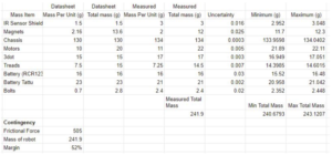
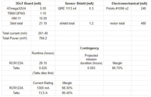
The power resource report shows that neither the Tattu 7.4V battery nor the 3DoT’s battery will die before the E-Racer finishes its mission. It also shows that the batteries will not draw more than their rated current. The current drawn by the motors was calculated assuming that the E-Racer is climbing directly up the wall. The actual current drawn during the test should be less.
Project Report
In this section, we will find our work breakdown structure and our product breakdown structure. You will also find our budget and schedule for this semesters project.
Project WBS and PBS
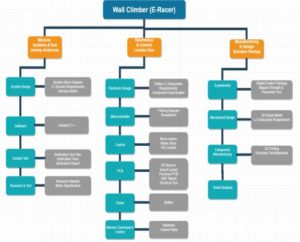
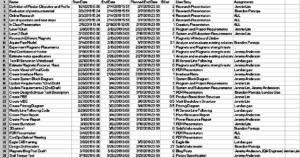
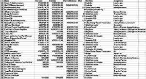
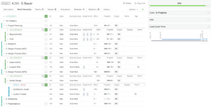
The WBS shows the different tasks each division is responsible for. The Missions Systems and Test are responsible for the System Requirement, Project Allocation, and Verification/Validation. Electronics & Control is responsible for the PCB design, software, and implementation of the 3DoT board. Manufacturing is responsible for designing the chassis for the robot.
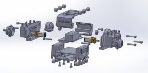
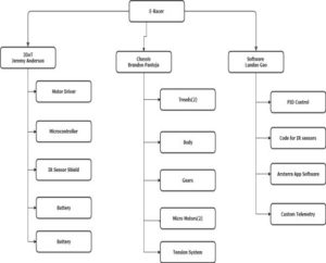
The E-Racer PBS breaks down into primarily three parts: 3DoT, Chassis, and Software. The software includes the code for PID line following, RC mode, and the telemetry for switching between autonomous and RC. The chassis includes the motors, treads, tensioner system, and gears. The 3DoT contains the microcontroller, Bluetooth module, battery, and motor driver.
Cost
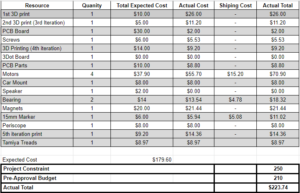
E-Racer’s project cost constraint is $250. Most of the cost of our budget came from 3D printing. There are four print orders of various materials from the CSULB Library Innovation Space. The first print cost $26 because we did not know that each file would be charged a minimum of $5. The other items bought include custom PCB, SMD components, 210:1 micro gear motors, bearings, car mount, 15mm marker, Tamiya treads, and a periscope. The bearings and motors were the second most expensive items per piece. The bearings were used to reduce the friction of the big idler wheels. The micro gear motors were bought for their small size and gear ratio.
Schedule
Burndown and/or Percent Complete
Concept and Preliminary Design
Referencing the Goliath 302 Tank and previous semester’s Goliath design, Brandon started from scratch with his own version at a smaller scale than the previous Goliath, Generation 5. The project was constrained to be smaller than previous generations and to closely fit a 3DoT board.
Literature Review
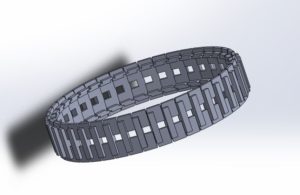
To begin our objective, we referenced Generation 3 and Generation 5 SolidWorks files to visualize the model parts that make up the whole tank from Arxterra website and referenced back to the images of the actual Goliath 302 Tank. We found that their scale was not accurate because it was shaped more like a square compared to the real Goliath tank. So the first 2 designs we made, used a new scale size, but to keep it accurately scaled and as small as possible, the treads needed to be smaller. A custom tread was 3D modeled, but Jeff suggested we keep using Tamiya treads. He was concerned that since the model was so small, creating custom treads would require a small enough resolution from the 3D printer to capture the joints where each piece of the tread is joined.
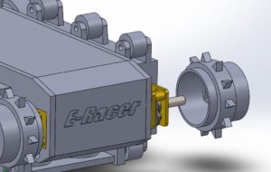
Due to the size constraints, the motors had to stick out of the robot more than previous generations, causing the wheels to not align with the treads. To fix this, we implemented a hollow sprocket wheel design similar to Sojourner, where the wheel would encase the motor allowing the teeth of the sprocket to align with the tensioners.
Design Innovation
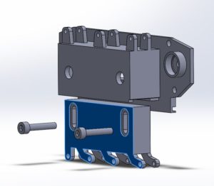
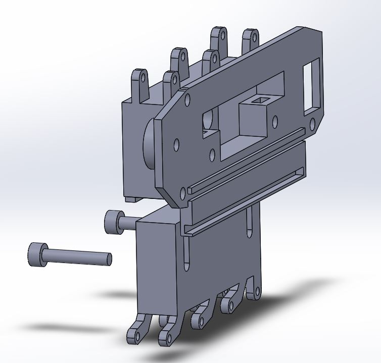
One problem all the other generations have faced was tensioning. Tamiya treads are only able to be modified in length by set increments since it is an off the shelf product. So in this generation, we introduced a tensioning system for Tamiya treads that slides in a vertical motion to adjust the tension.
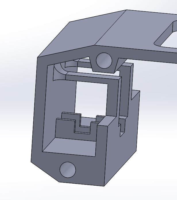
From the picture above we can visualize how the nut capture insert where the nuts slide into and grab the bolt; when the moving block is pressed against the inner wall of the hollow space.
Also, another issue with the previous semester was not implementing the use of bearings to the extent of reducing the amount of friction present as the big idler wheels are spinning.
- Big Idler Wheels with Bearings
- Low friction, freely spinning idler wheels
- Avoid the use of axles
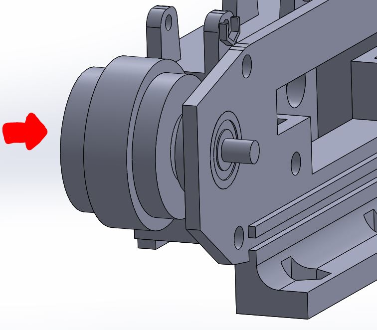
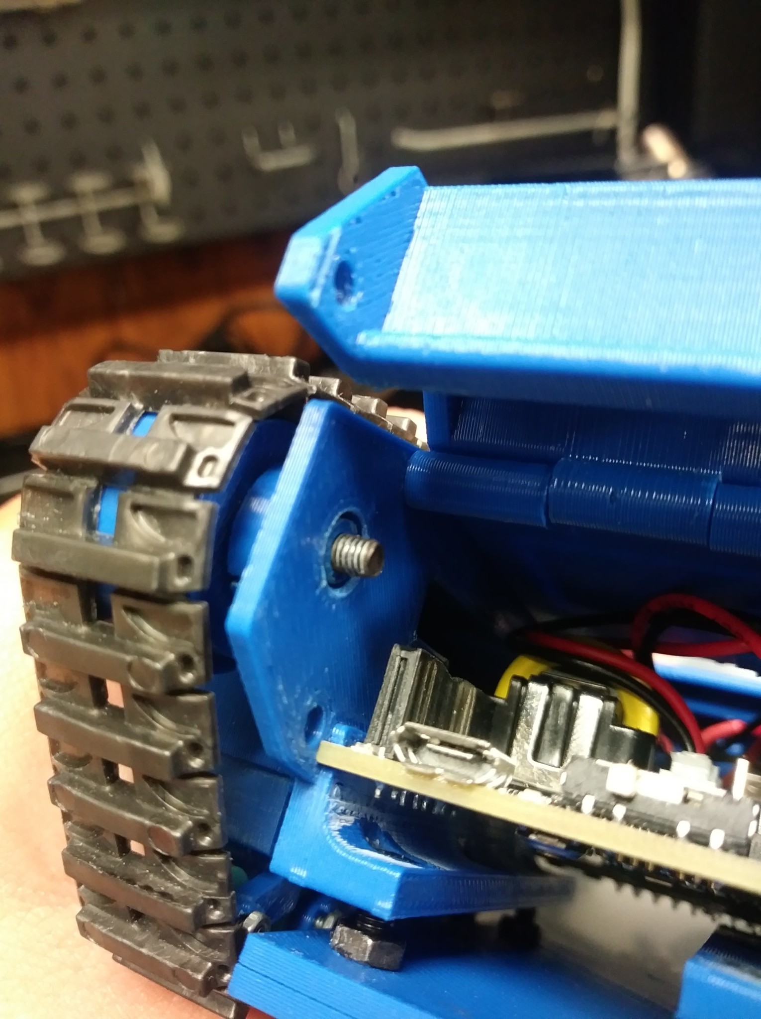
As seen from the picture above the bolt slides in from the outside surface of the big idler wheel as indicated by the red arrow and inside a cup-like insert on the side panel a 10mm diameter ball bearing is press-fitted. The end of the bolt is then secured with a nut. The trick to this design was to only make sure the inner race of the bearing is spinning freely, and it was achieved. The nut only grabs the inner race when tightened and on the other side, a small fillet was added to the idler wheel so that a small circular shape will press against the inner race of the bearing.
Conceptual Design / Proposed Solution
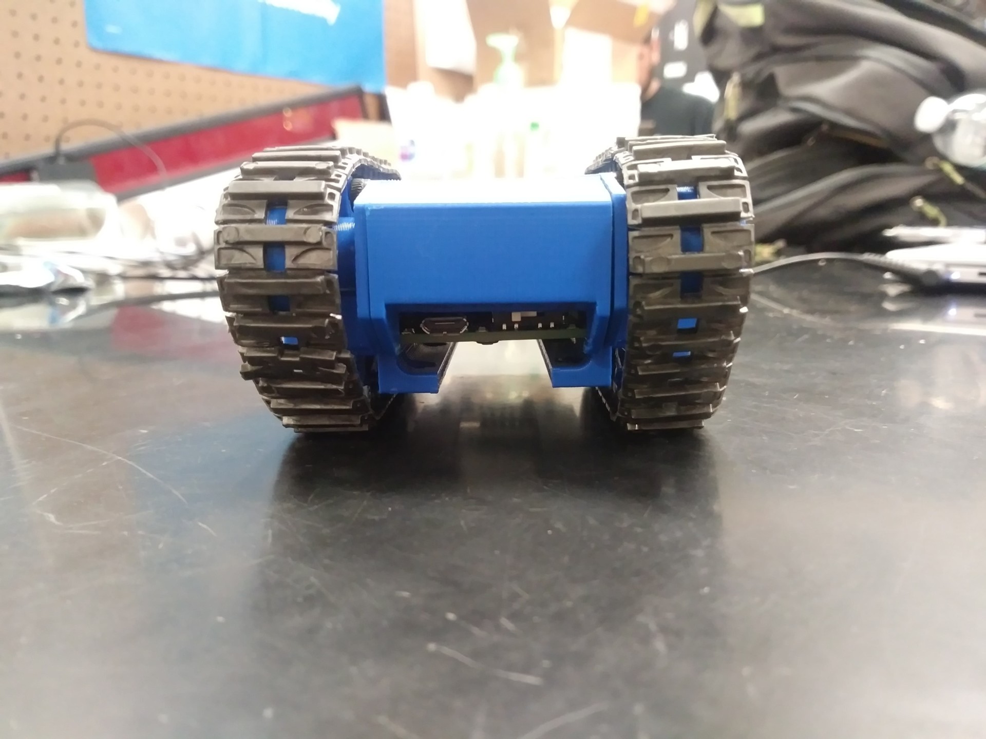
One of our main objectives was to make the base of the robot so small that it holds just the 3DoT. To achieve this we designed the robot to slide in the 3DoT and have it act as the base of the robot. This helped keep the robot small and played into achieving the requirement to have immediate access to the external connectors. A door panel was created to easily slide in the 3DoT and keep it in place when closed. Also, our customer was unhappy with using wires to hold the small tensioner wheels. So we replaced them with small bolts and nuts.
Aside from the changes mentioned above, the other components of the robot are almost the same as the past generations but have been modified to provide more support. The components modified:
- Tensioner legs
- Added partial nut captures
- Reinforced at the base to not break so easily
- Motor housing
- Added a brace to hold the back of the motor to prevent tilting
- Added a small curved wall to prevent the motors from clashing
- Cable insert
- A small loop to thread the motor wires through to keep them in place is found on the inner wall of the top panel.
- Aesthetics
- Artistic elements added to look like a real tank
System Design / Final Design and Results
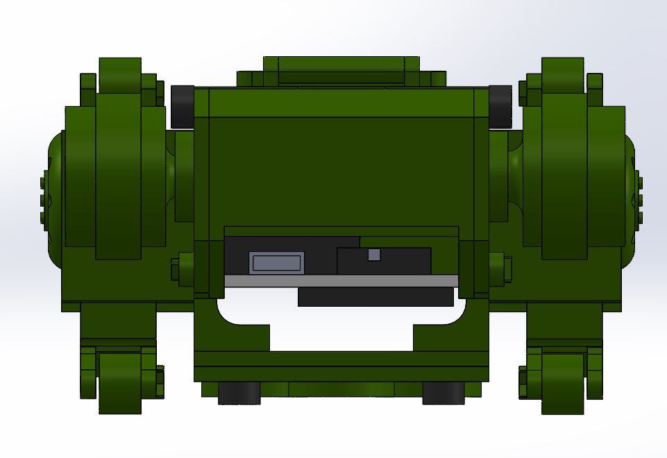
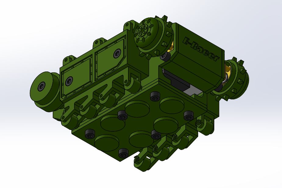
For our final design, we have the hollow sprocket wheels, tensioner system, door panel, magnet plate, and 3DoT base. The hollow sprocket wheel were designed to encase the micro gear motors to allow the robot’s body to stay slim and align with the idler wheels. The tensioner system is designed so that the sides are hollow and the bottom tensioner legs can slide in or out. When the treads are put onto the tank the tensioners are adjusted to the desired height then screwed into place from the sides. The door panel was created to easily slide the 3DoT into the robot and keep it in place. Also when closed, the door panel has an opening that provide immediate access to the external connectors such as the switch and usb port. The magnet plate was made to hold 6 disk magnets with a cap plate to prevent the magnets from accidently pulling itself out due to its strong magnetic force. It hung below the tank with bolts and nuts to make the distance from the board adjustable. It is adjustable because the tensioner system could alter the height of the robot and the magnetic force changes greatly with even the smallest change in distance from the board. The 3DoT base, inspired by the PaperBot, was implemented because it provided a form of secure mounting for the 3DoT and easy access to the external connectors.
For more information check out our design blog post.
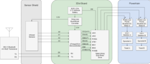
System Block Diagram
Interface Definition
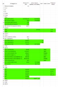
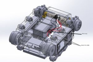
The interface matrix is essentially the same as the 3DoT interface Matrix found in the EE444 lecture but slightly adjusted to match our project. The only cables in our robot are the cables from the motors which connect to the 3DoT board. In the cable tree, the wires curve a bit and are threaded through the cable loop. They are kept long enough so the 3Dot board can be partially pulled out to unplug the motors. There will be two additional cables if the speaker is included.
Mission Command and Control
3DoT Robots
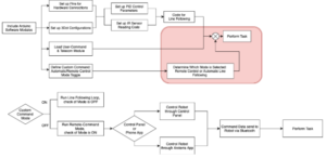
This section provides a systems level look at the software modules employed by 3DoT robots. This section represents a collaborative effort by the system and electronics/control engineers.
| Hardware | Software |
| Personal Computer | Arxterra Control Panel |
| Smartphone | ArxRobot App |
| 3DoT Board | Arduino and Robot3DoT Library |
Electronic Design
PCB Design
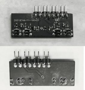
The purpose of this PCB design is to design an IR Sensor Shield for four QRE1113 IR reflectance sensors to accomplish line following tasks. The original idea came from a product that was used in EE444 class – Sparkfun QRE1113 Digital Breakout Board. Due to the design requirements, the breakout boards are too big to fit in our robot scale, hence this new IR Sensor shield design.
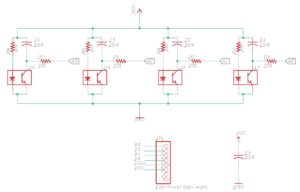
This design contains four capacitor discharge circuits, which each contains one 100 ohm resistor, one 220 ohm resistor, one 10nF capacitor, and one QRE IR Sensor. The reason for these choices was made with the reference to Sparkfun QRE1113 Digital Breakout Board’s capacitor discharge circuit design. To keep the design efficient and fit the size requirement, no other components were added.
This design measures the amount of reflection from a capacitor discharge circuit. When the power is supplied, the IR LED inside the sensor will illuminate, the phototransistor connected to the 10nF capacitor will receive reflection then cause the capacitor to discharge. Finally, the microcontroller receives discharge rate and output the numbers, the faster that capacitor discharges, the more reflective(lighter color) the surface is.
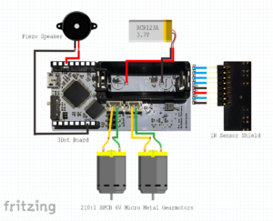
The design was initially tested on a breadboard with a Sparkfun Pro Micro board, the Fritzing diagram is shown below.
Then, the PCB schematics are designed using EagleCAD. An additional 10uF capacitor that connected directly between VCC and GND is added to the design to reduce the impact of the current spikes during the switching, and also provides a low impedance path to ground to reduce noise from signals.
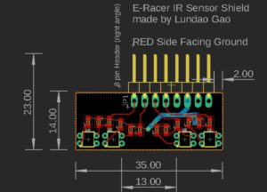
From the design of line following code and previous tests, the layout of IR sensors are determined as two pairs of IR sensors 15mm apart from each other and sensors in each pair are next to each other. In order to fit with overall robot design, the width of the PCB was determined to be 35mm, which is the same as the 3DoT board. The PCB is also designed to have 2 layers with polygon to have higher efficiency on the power supplying and noise reducing. All resistors and capacitors are chosen to be the size of 0603 and surface-mount. All IR sensors and headers are rated size and through-hole mounted, since they will be handled a lot, in order to provide better overall quality, through-hole design for these components is a more secure option and ensure to cause minimum damage when handling, as advised by the TA. The final PCB layout design is shown below.
Firmware
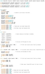
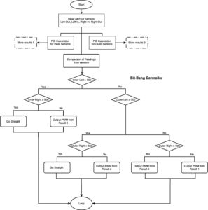
Firmware implemented in this project is Line Following and PID Calculation. Line following and PID code were accomplished with an Arduino PID library. It allows the user to customize the PID coefficients and the set points in order to smoothly follow the line.
Mechanical/Hardware Design
For the final design here is a list of the key features of the overall project:
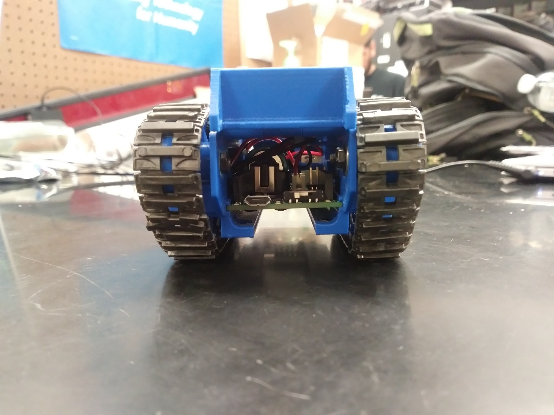
- Door Panel: Allows for quick access to the USB port and On/Off switch, as well as serve as an entrance for the 3 dot board to slide into and serves as a holder to keep the 3DoT in place.
- Tension System: Allows the tank treads to stretch further; therefore, provide better movement overall of the tank to prevent snagging. To compensate for ride height issues caused by this tension system the magnet plate was redesigned to be adjusted vertically and ultimately move closer to the surface of the whiteboard.
- Big Idler Wheels: Referencing back to previous semester’s design, they would use a metal axle to connect the two idler wheels through the two plastic side panels. However, this caused an issue in the friction produced as the tank experienced motion. This new design was fixed with the implementation of 3M ball bearings, thus establishing a foundation to mount each idler wheel individual of the other and spin freely without much friction as the idler spins on the inner race of the bearing.
- Hollow Sprocket Drive Wheels: To accommodate for the narrow inner width of the tank that fits the 3DoT perfectly, The motors no longer fully fit inside the motor housing so the gearboxes stick out. The design from Sojourner’s wheel assembly was implemented into this design where essentially a “hollow” sprocket wheel encases the gearbox; therefore, allowing it to stick out of the motor housing.
- Overall Scale: Although our tread width is slightly off, the overall dimensions of this design are much more accurate in scale to the real Goliath 302 Tank; ultimately, highlighting its narrow inner width and extruded length.
*Several iterations were performed as part of the engineering method and design process, before this final product. It can be seen here…
The Final Design
The following images showcase the fourth prototype, the closest looking version compared to the final (slight changes were made in the 5th (final) iteration):
Prototype 3 design (shown below to highlight key aesthetic and mechanical modifications improved on with Prototype 4)
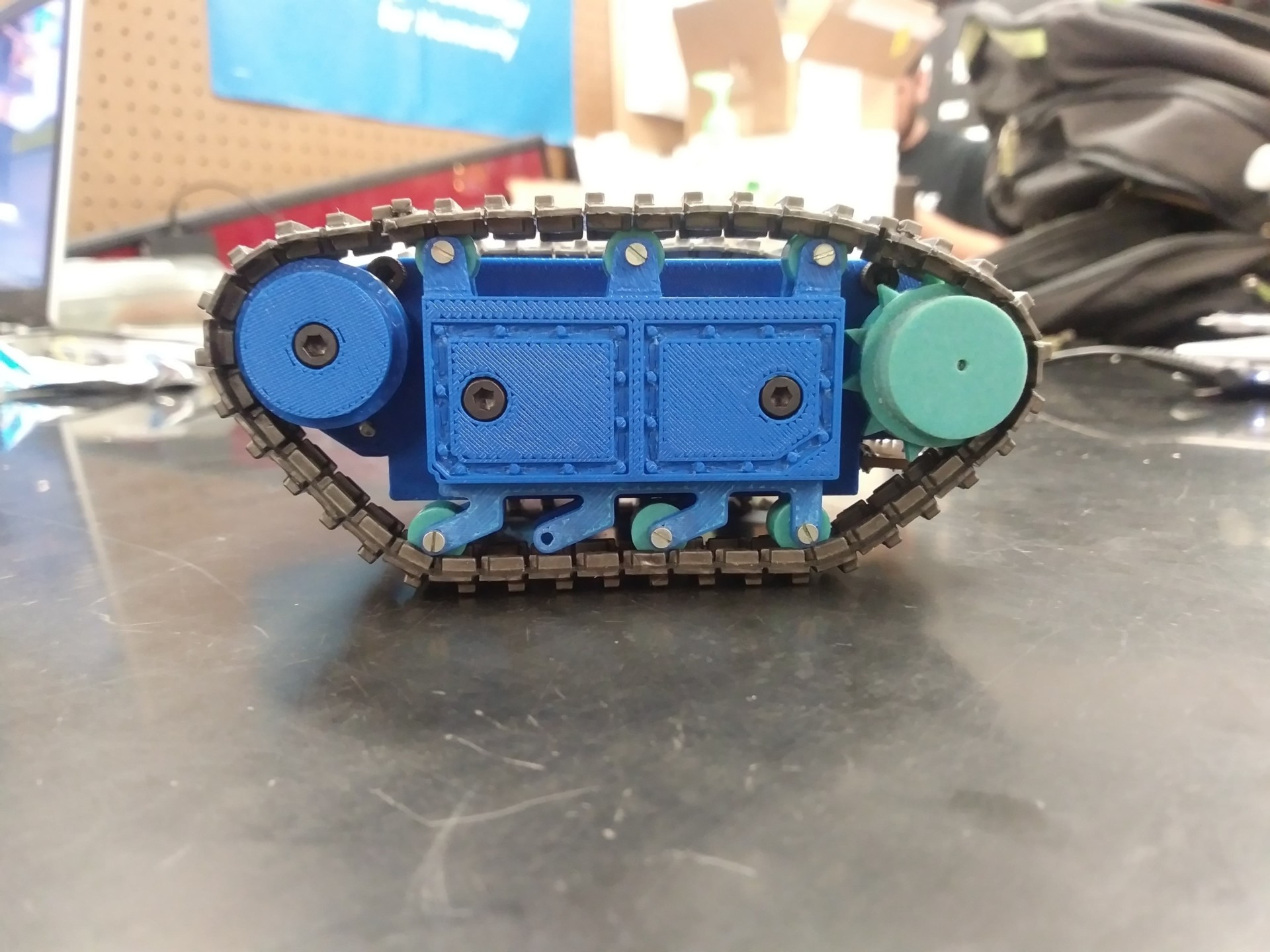
Different angles of Prototype 4:
It can be seen from the 1st picture below, from a side view of the tank, how the tension system works, with two 20 mm long bolts (including head) that are tightened to press against the inner sliding block that contains the 4 small tension arms.
The picture below illustrates one initial design of the bearing system, where now in the final print the bearings slide in from the inner wall of the side panel as mentioned before.
The pictures below illustrate the door panel opened and closed. The sleek design shows how thin or narrow the inner width of this tank is, which highlights a feature of the real Goliath tank.
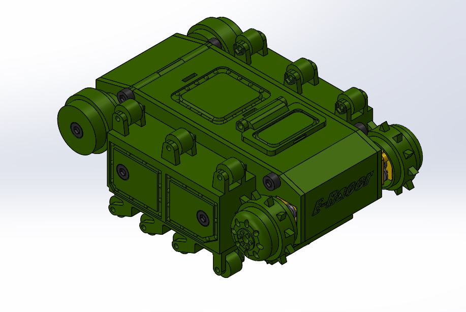
Solid Works screenshots of Final Product (final print arriving the day before final):
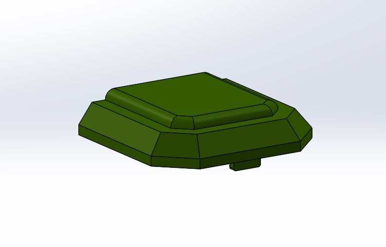
The added top door hatch can be seen from the picture above.
From the picture above, new door panel holders were designed to avoid the use of bolts.
The picture above showing the magnet plate assembly.
The following image of the robot has a top panel that is used to hold the phone as well as highlight a key feature in a certain version of the Goliath 302 tank, so the design is still following guidelines on depicting the actual Goliath tank. The final design also includes big idler wheels with teeth just in case the tracks slip off and we need something to keep them on.
Overall the robot seems to successfully demonstrate the movement and aesthetics of the Goliath tank; the wall climbing aspect has some issues, we will try and implement small magnets on the treads to further allow grip and better movement on the wall; however, if its not possible then this would be a perfect modification to be done in the future to enhance the mobility and grip of the tank on the whiteboard.
Verification & Validation Test Plan
In E-Racer’s test plan, there are three test cases label as TC-01 Operation Tests, TC-02 Visual Based Tests, and TC-03 Mission Execution Tests. All the test cases are performed in a classroom environment either on the ground or on the whiteboard. The purpose of TC-01 is to show that the E-Racer can function properly without the challenge of climbing the whiteboard. In TC-02, we verify if we meet requirements related to physical appearances and size by mostly inspection. The requirements verified in TC-03 are those related to the mission performed primarily on the whiteboard. The TC-01 will show us what can be done, but TC-03 see if it can do those tasks on a whiteboard.
For more details see the V&V Test Plan.
Concluding Thoughts and Future Work
Future Improvements:
- Use something else besides nuts & bolts to assemble robot
- Reduce the weight
- Custom treads
Improving the three bullet points listed above will allow the robot to climb the whiteboard easier. The custom treads will reduce the size of the overall tank. Also the custom treads could be designed to implement tiny magnets in the tread to improve traction on the whiteboard.
Tips:
- Label all extrusions in SolidWorks
- Smart dimension could not only be used to specify the size of the part but also the position of the part. You can do this by clicking the edge of the part and the of something to specify how far you want to make the first part from the second part.
- You can save all the parts in assembly as one part by click options and checking the “save as one part” box when saving your assembly as an STL file.
- Save money at the library by putting all parts in one STL file (min per file $5)
- Future managers don’t be afraid to assign tasks to your group. Check on them to make sure they are on track and on time. Make sure you see proof of what they say they are doing/did.
References/Resources
- Resources (Code, Eagle, & Solidworks files)

