E-Racer/Spring/2019
E – Racer Spring 2019 Mechanical Design
Author: Brandon Pantoja
Verification: Jennie Lim
Introduction
This blog post illustrates and explains the iterative design process under the engineering method; throughout the project E -Racer, a line following robot that moves on a whiteboard. Designing a product under strict requirements posed a challenge to my group and myself personally because we had to meet the satisfaction of the customer. The iterative process; however, reveals the overall improved and exceptional product that can be made. As Manufacturing and Design Engineer, I learned to adapt the iterative design process, and through the engineering method I was able to complete our desired product, of a scaled down version of a Goliath 302 tank, that climbs a whiteboard.
Initial Designs
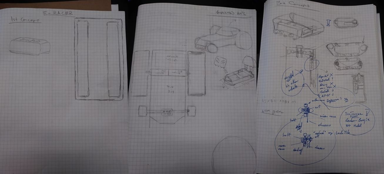
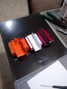
Beginning the semester, we had intentions of making a robot that would travel along the whiteboard surface. I took some time to rapid prototype some models using miscellaneous parts that I had and was lent. As seen from the pictures I designed two different robots, that were small enough and light enough to attach and move on a vertical surface. I noticed that the treads provided good friction to grab and move the robot along the whiteboard. With these 2 design iterations, I was trying to see what size and weight I needed to have to be able to stick to the wall and move, as well as test the friction of rubber tires and tracks for a tank, as part of the engineering method. Eventually, I settled on the Goliath tank body to perform this task. I was demonstrating the engineering method performing these tasks and I learned from my mistakes.
Choosing Goliath Design
Concept and Preliminary Design
Referencing the actual Goliath 302 Tank and previous semester’s Goliath design, I started from scratch with my own version at a smaller scale than the previous semester, Generation 5. This was in tie to the requirement of being smaller in size and being able to still fit a 3 dot board. I did not use previous solid works files because I had difficulty with SolidWorks program not having used it in a while; however, by the time I got to Proto 2 I picked up the pace and improvement was seen.
Prototype 1
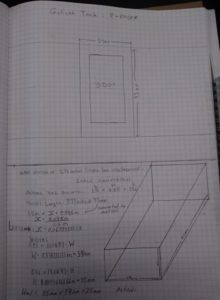
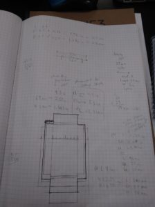
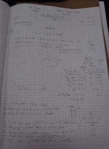
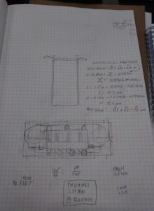
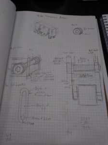
In order to meet the requirements of having a scaled-down version of the real Goliath 302 Tank, I had to make some calculations as seen from the picture above. To do this I referenced the length of the 3 Dot Board to accommodate for the real dimensions of the tank (L:1.5 x W:0.85 x H:o.56 meters). Once I found the scale ratio indicated by LRATIO , I was able to find the new scaled down dimensions of the tank. It resulted in a scale factor of 0.63, which was smaller than the previous generations.
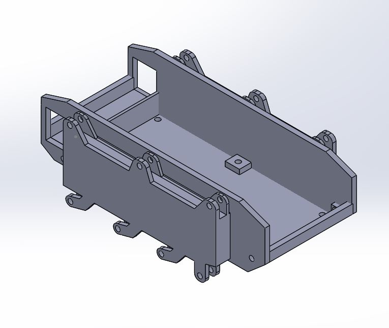
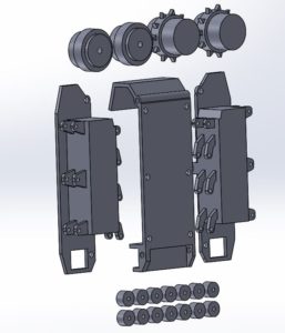
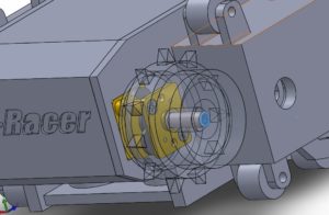
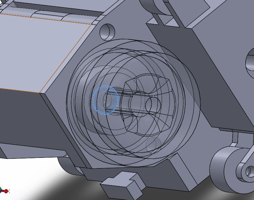
Motor gearbox sticks out of motor housing to accommodate for smaller width tank and have the 3 dot slide in and touch side walls. Design for hollow sprockets came from Sojourner design. With this design, we can have a smaller width tank. Essentially, the goal was to have a small enough inner width to flush fit a 3 dot board into.
Learned from previous rapid prototypes:
- Goliath proved successful in traction and weight
- Big wheels and small wheels for the second concept combined caused tipping when it climbed the wall
- All 4 big wheels design was too heavy, and the motors used provided very little torque to climb the wall
- Sometimes using tools or parts that you have available don’t pan out as well; however, well-documented info and previous material from Goliath was very helpful
Design Flaws of Proto 1:
- Track widths too small (scaled but not proportioned)
- Learned to make the scale slightly bigger and make 3dot width the scale reference as opposed to the length as seen from calculations when finding the scale factor.
Prototype 2
At this point, finding the point of interest where the tank is smaller than the previous semester and smallest overall, while still retaining proportion, from this new smaller scale.
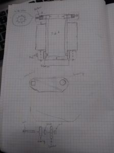
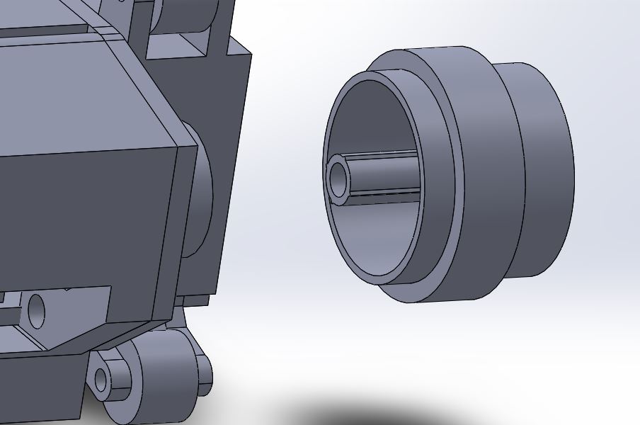
I worked alongside MST: Jeremy Anderson, to create the new hollow sprocket drive wheels. We had to find the ratios of (number of teeth) to (sprocket radius in millimeters) referencing back to the Tamiya set of sprocket wheels provided from Professor Hill. We discovered that they had a ratio of (1 tooth) per (1mm radius). Measuring the radius was done using a caliper. We can see from the picture provided above, how the drive wheel encases the gearbox of the motor. This design allows for the teeth to align with the small tension arms that hold the small idler wheels.
Modifications from previous design:
- Side panels extended to compensate for track width
- Open slot below motor housing to allow 3Dot board female headers to connect to custom PCB
- Created big idler wheels and drive (sprocket) wheel
- Sprocket drive wheel design:
- Teeth were created in reference to Tamiya toy set wheels
- Made them hollow so that motor gear housing can sit inside
- Sprocket drive wheel design:
Design flaws of Prototype 2:
- 3 Dot insert was not established and unclear
- 3D print did not come out very well, not good for testing
- Bearing holders were not good, clip-like design
Prototype 3
Up to this point in the iterative design process, the picture below denotes the several models of Goliath tanks. Starting from far left is the Goliath Gen 5 from the previous semester, then a paper model I made of the proper dimensions for Prototype 3 (final scale); finally, the print of Prototype 1. They are side by side to see the size difference. Although I made the final scale as seen from Figure 13 slightly bigger than Prototype 1; it still remains smaller than the previous generation.
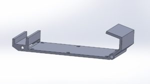
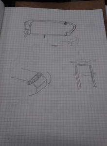
Figuring out quick access 3Dot design, ended up going with door panel design came up from previous talk about cupboard like design to slide 3 dot in and out, so I decided to make something that will hold the 3 dot in place and keep from falling out as well as be able to put and take the 3 dot in and out
The following design came to mind:
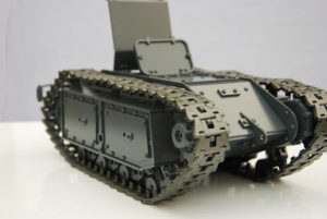
It is important to notice that I moved away from the traditional design of clamping the top panel and bottom panel together as previous semesters did. However, this design is quite inaccurate. I learned later on when I added aesthetic features to the tank during Prototype 4 stage and referenced the following image from Figure 16 that the Goliath tank actually does have a door panel. To my luck, and keeping the most realistic attributes of the tank, the door panel proved successful.
Another key point to mention form this new 3DoT insert and quick access assembly is that now the overall tank can be seen as 3 main parts. The two side panels and the top panel which includes the motor housing and door panel; as opposed to previous designs where 4 main parts were required to assemble the robot: the top panel, bottom panel, and two side panels. I was able to meet this realization because of the implementation of the 3DoT acting as an external base of the tank, which was inspired by the Paper Bot design.
Another important feature discovered in this prototype is the application of bearings to spin and attach the big idler wheels too. The following designs were made:
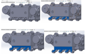
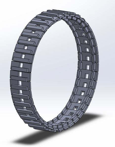
I also had the task of making custom treads for this robot. However, it proved to be difficult after talking with Jeff and Professor Hill at AoSA. Jeff’s reasoning was that the printer had to have small enough resolution to be able to print the small material that holds each individual tread piece that makes up the whole track. Because the robot is so small, making tracks smaller than Tamiya proved difficult. Below is the design I made of the custom treads with the help of MST Jeremy, referencing back to the Tamiya treads and cutting off the sides to make them look thinner. I started with one tread piece, measuring out the Tamiya tread, and once one tread piece was complete, I created a plane down the center so that I can make a circular pattern with a radius of 40mm; which was the measured circumference of the wheel assembly on the side panels.
The following image shows the print of Prototype 3 from PolyJet material, it was a very clean print and with this prototype we were able to do some small tests of climbing on the whiteboard.
Modifications from the previous prototype:
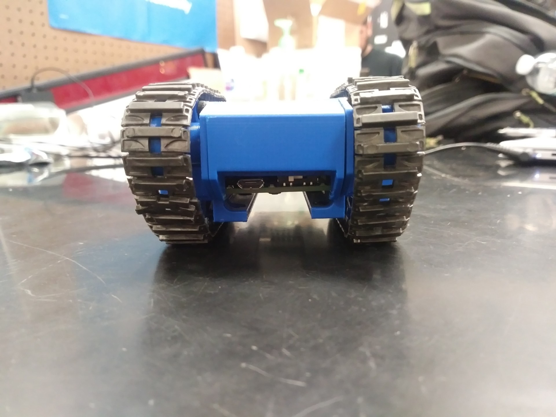
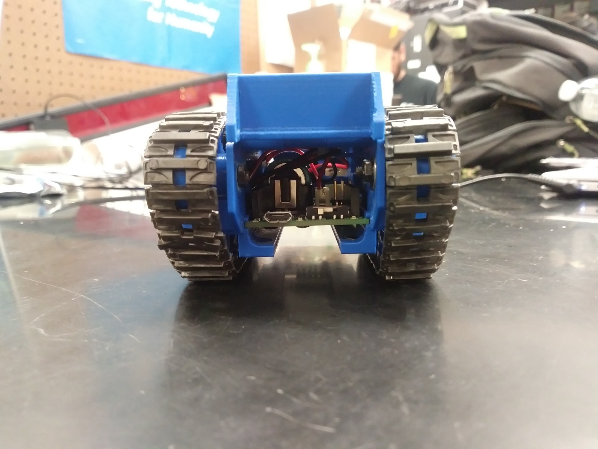
- Door panel (quick access to 3 dot board) this was designed this way because it serves as quick access to USB and switch, as well as a holder of the 3DoT to keep from falling out when in a vertical motion
- 3Dot insertion inspired by the Paperbot design
- Top panel and motor housing are 1 piece
- Added the bearing capture which will turn the big idler wheels with less friction
- Side tension mechanism design, but not in 3Dprint at that time when presenting CDR
Design flaws of Prototype 3:
- Magnet plate needs to be placed closer to whiteboard surface; around small idler wheel level
- Need a method to hold the big idler wheels to side panels through the bearing (use of bolts and nuts required)
- Need to hollow outside panel blocks, make the robot-heavy
- Need to find hardware and apply for small tension arms and wheels
- Motor housing did not keep motors steady, they would tilt (redesign needed)
- The model needs aesthetic modification (make look like an actual tank)
- Tension system needs to be tested (design but no print at the time)
Prototype 4
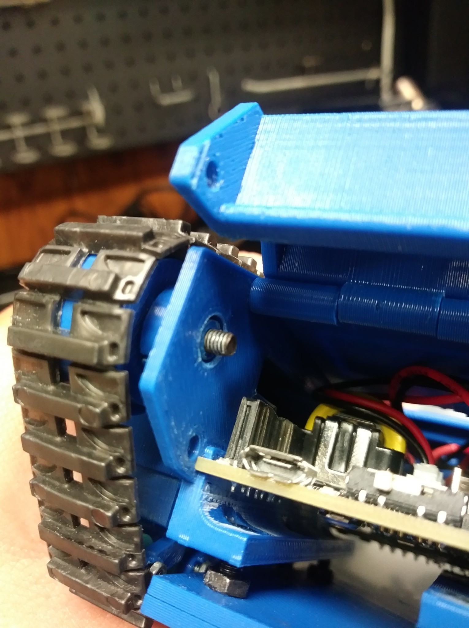
Bearing installment was altered from this design to have the bearing slide into the pocket seen from the inside of the side panel and remain flush so that the door panel will hold the bearing in place and keep from falling out, where only the outside trace of the whole bearing is being held stationary, only inner race is freely moving.
In the picture above, we can finally see the tension system on a print and works as its intended to.
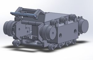
The two picture below show the door panel features, when closed it keeps the 3 Dot Board from falling out and provides quick access to the USB port and On/Off Switch. When open we are able to slide the 3 Dot Board in and out of the robot.
Modifications from previous design:
- Added support on the tension arms because the previous prototype broke off one of the small tension arms
- Pulled bottom row of tension arms out more towards the ground to move wheels away from side panel rectangular piece, because they were rubbing from Prototype 3
- Added nut captures to hold the nut in place on the small tension arms for the bolt axle
- Added artistic touch
- Fixed the motor housing keep the motors from wobbling (as noted from before)
- Fixed big idler wheel and bearing installment (after talking with Jeff and Professor Hill)
- Fixed the magnet plate attachment to allow variability with height away from white board and match ride height when tension system is in effect
Final Design
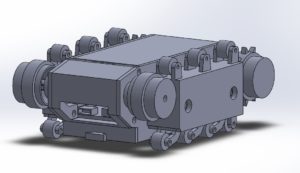
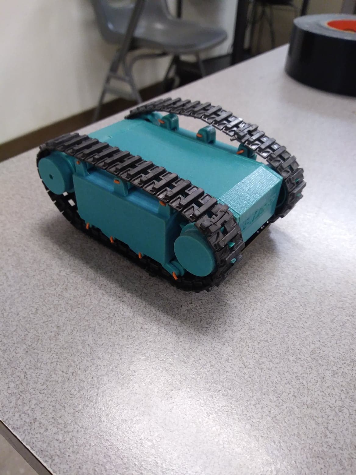
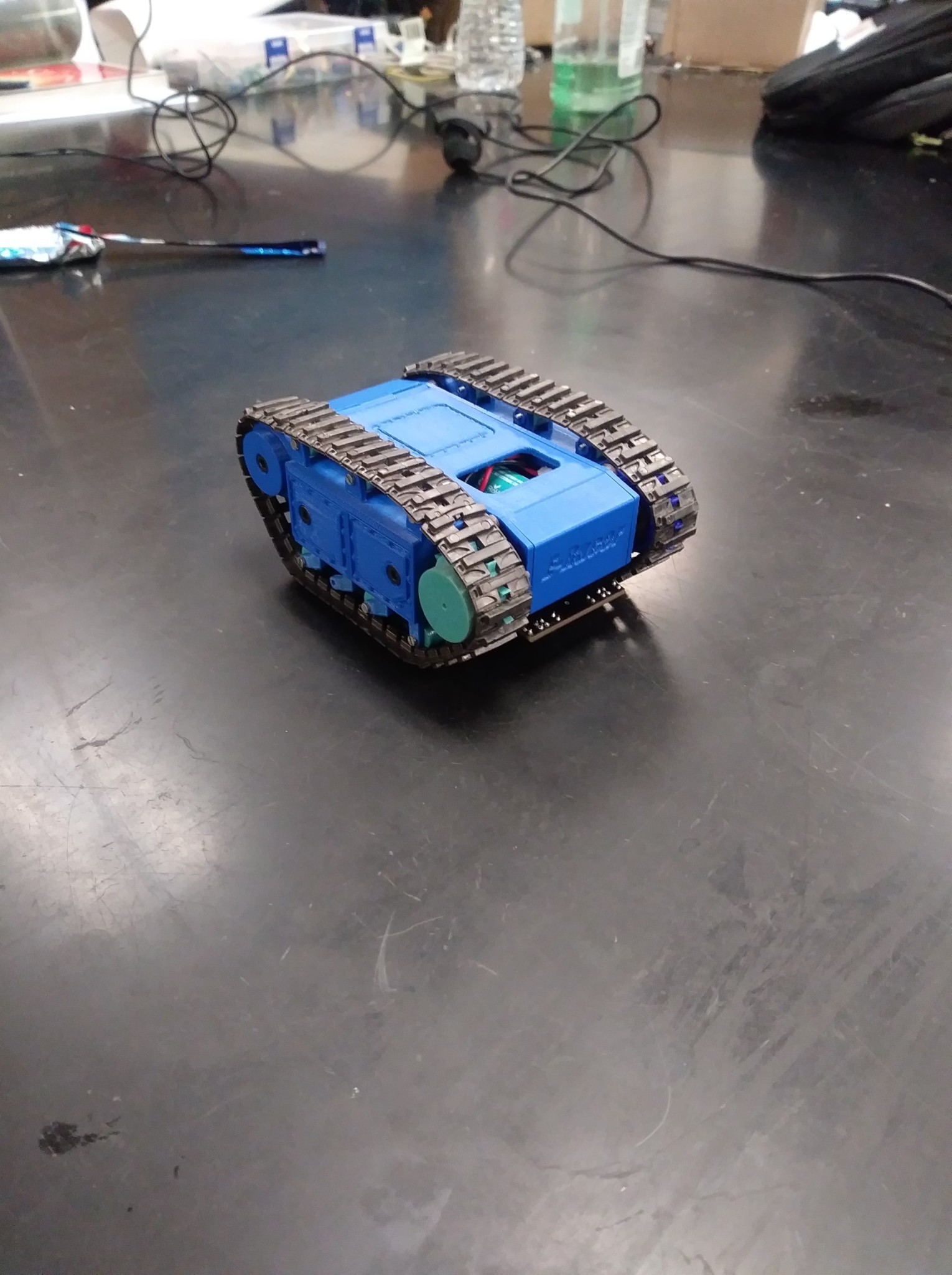
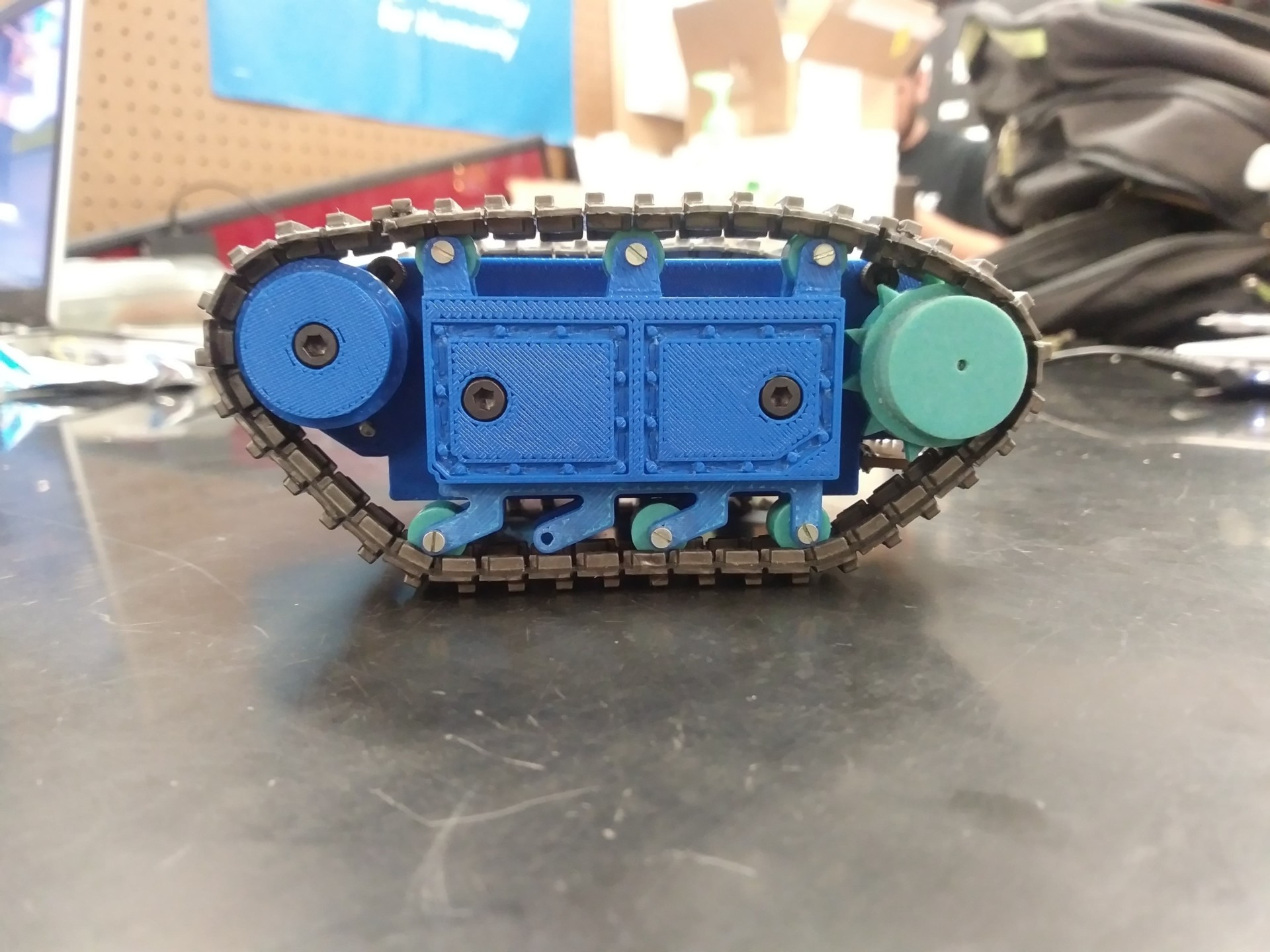
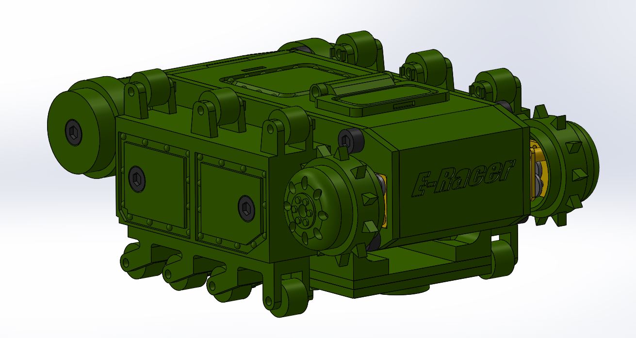
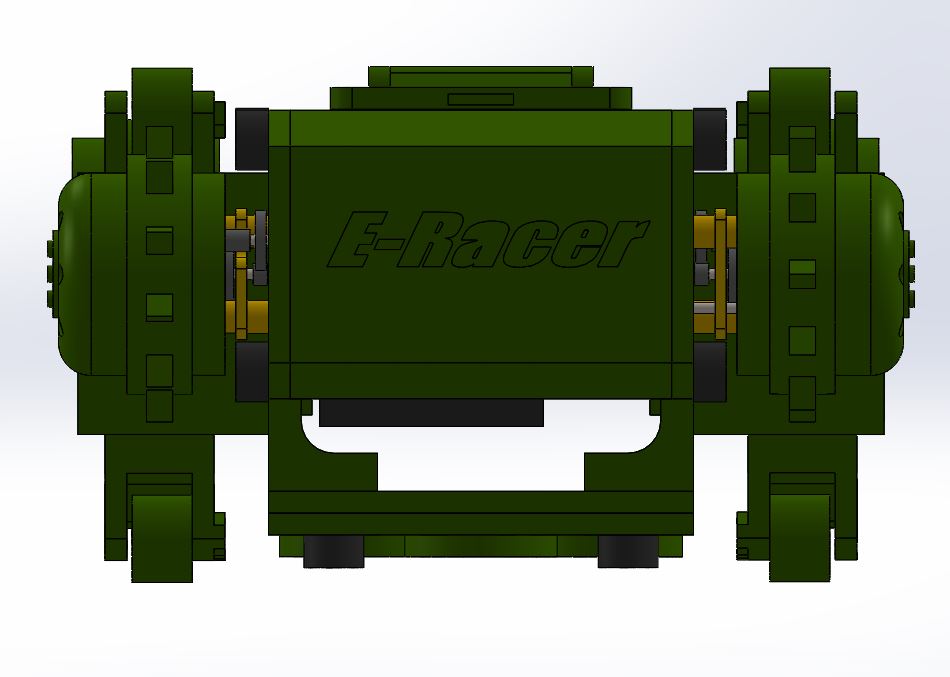
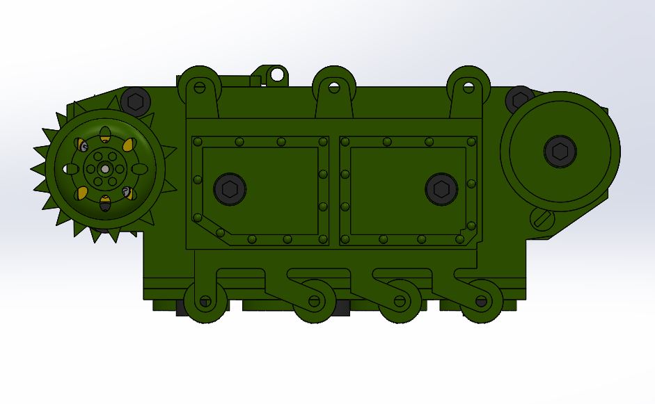
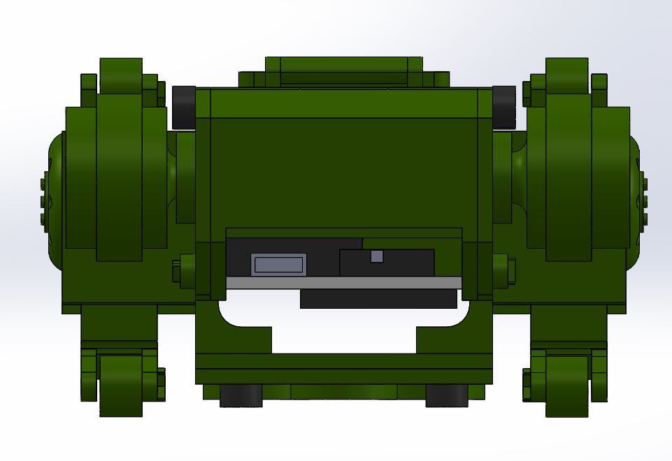
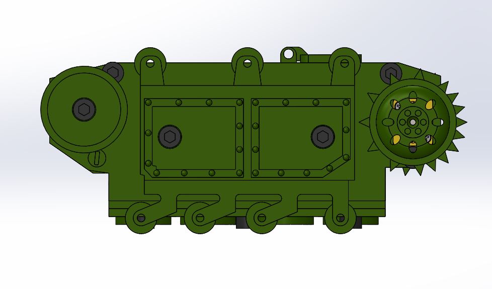
To conclude the semester, we have now reached the final design, after much iterative tasks, to finally reveal a scaled down version of the Goliath 302 Tank: with a quick access and easy insert 3 dot mechanism, low friction big idler wheels, hollow drive wheels, and tension system; where all four of these things I consider the main important key features of this version of Goliath tank.
As seen from the figure above, I have now completed the aesthetics of the tank by implementing the top door hatch, as well as fix some minor parts such as: the small tension arms (added support), the motor housing (added support).
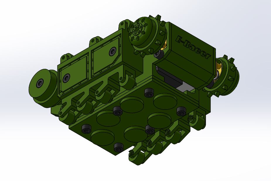
The figure above shows the magnet plate assembly; held on with 6 bolts and with nut captures at the ends to hold the bolts in place. This design was implemented since Proto 4, to essentially allow the robot to climb on the wall and stay attached to it.
Conclusion
Through this mechanical iterative design process, I have learned the importance of scheduling as well as why several projects take time. The multiple iterations of prototyping reveal mistakes made as well as improvements. By 3D printing the designs made on Solid Works we are able to test the mechanical aspects of the robot. Also, an important action to take in the design process is to have access to a 3D Printer and make multiple prints immediately, after making modifications. It is also very important to talk with the customer and follow guidelines and requirements to ultimately, achieve a fully operational product.

