Eagle CAD Training
By: Diane Kim (Division Manager of E&C Hardware)
Verified By: Jordan Smallwood (Pathfinder Project Manager)
Approved By: Miguel Garcia (Quality Assurance)
Table of Contents
Introduction
Eagle is a program used to design and layout custom boards. We went through a series of training for using Eagle CAD.
Training 1: Schematic
The first training was based off the documentation from Sparkfun. It was focused on designing the schematic. These were the points of the program that we went over:
- Adding the components
- Package, type, and SMD or Through-Hole
- Moving and rotating the components
- Connecting the components use the “NET” function
- Deleting and copying the components
- Labeling and naming the components and the values
- Adding new libraries
- Using the ERC command
Figure 1: Toolbar of the Eagle Schematic
Training 2: Board
The second training was focused on designing the board layout. These are the key points that were went over.
- Layers: Top and bottom
- Routing the layers
- Auto-routing
- Placing the components
- Talk about Female and Male header connections
- Possible restrictions (Size, placements, drill size and trace size)
- DRC command
- Copper pours for GND and PWR
- Effective GND and PWR connection
Figure 2: Toolbar for Eagle Board
Training 3: Practice
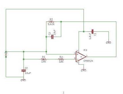
This training was focused on applying what was learned. The first practice was done together where a simple low filter schematic was given to design on Eagle.
Figure 3: Low Pass Filter Schematic using Operational Amplifier
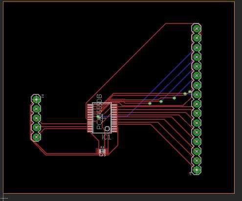
After the first practice, the second assignments were given as homework. The second assignment given was to design an I/O expander circuit.
Figure 4: Board Design of I/O Expander HW assignment
Training 4: Quiz
For the last part of the application, I assigned two quizzes. Each quiz was 40 minutes long and were given a simple circuit to design on the schematic and board. There were certain restrictions such as the mil size, the placement of the connectors, the size of the board, and the components’ packages. The grading criteria is the following:
- Did you follow the schematic?
- Did you follow the instructions? (such as package size)
- Is the position of the connectors appropriate?
- The overall quality
- Did you route everything?
- Did you ground the board or did you add the copper pours?
- Did you make it compact as possible? (Within the given size)
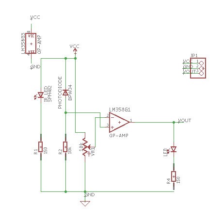
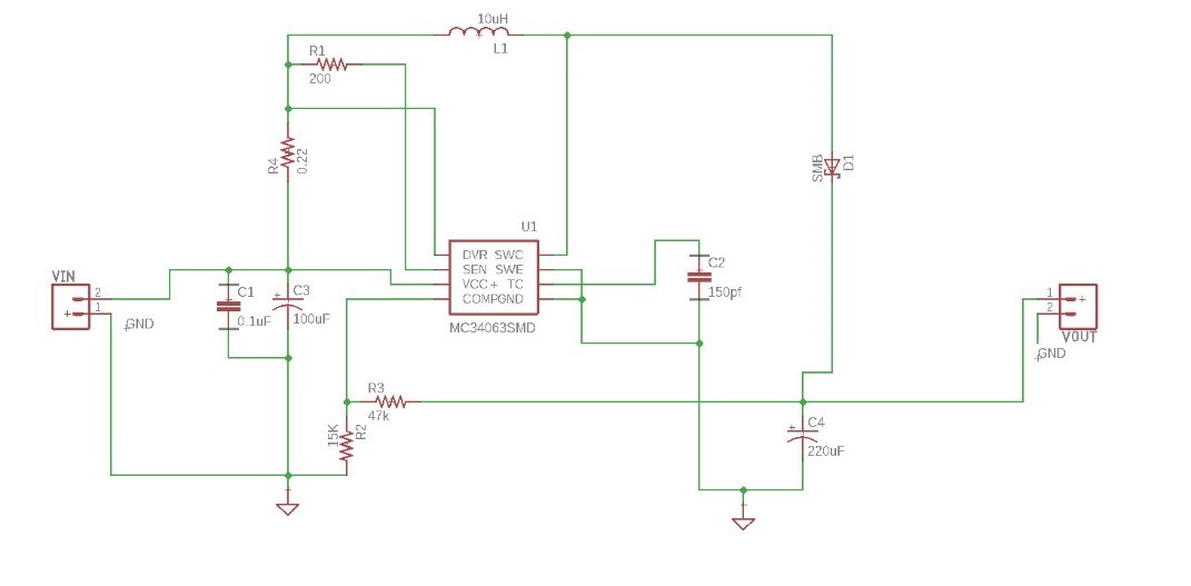
The first quiz was an IR sensor and the second is the boost converter. The schematics are shown below
Figure 5: Quiz 1, IR sensor
Figure 6: Quiz 2, Boost Converter


