Lab 2B — Build a Test Bench Direction Finder
Please quickly scan the lab before starting. This is a new class of lab that you can tailor to your own learning and academic goals. Specifically, you can follow a step-by-step or do-it-yourself approach – you decide. You can also decide how simple or difficult you would like to make the lab, based on the grade you would be happy receiving.
Table of Contents
Introduction
In the first part of this lab (Lab 02A) you designed a circuit with four (4) switches wired to four (4) LEDs of the 7-segment display. Using the four switches you were then able to draw all 16 rooms that the bear might encounter in his journey through the maze. This was the beginning of building your test bench to be used to verify the code you will write in future labs.
In the second part of the lab (Lab 02B) your goal is to design a digital circuit with two (2) switches that will turn on one of the rooms 4 LED segments indicating the direction you want your bear to walk. Like the previous lab, this code will become an important component of your test bench.
What is New?
Here are some of the new concepts you will be exploring in this lab.
- More Working with Bits
- Logical Instructions
- Conditional Branch Instructions
The following instructions and assembly directives are used in Labs 1 to 2. New items are underlined.
AVR Assembly Instructions
Data Transfer
ldi r16, 0x03 // Load immediate the number 3 into register r16
lds r16, dir // Load data from SRAM variable room into register r16
sts dir, r16 // Store data from register r16 into SRAM variable room
mov r8, r7 // Move data from register r7 into register r8
in r7, PINC // Input port C pins (0x09) into register R7
out PORTB, r7 // Output to Port B from register R7
Arithmetic and Logic
cpi a, 0x03 // compare immediate a with 0x03
cbr r16, 0xF0 // Logical and of r16 with complement of constant 0xF0
or r16, r17 // logical bit-wise or of r16 and r17, result placed in r16
com r16 // complement (not) of register r16
clr r16 // Clear register r16
ser r17 // Set register r17
Control Transfer
brne next_test // branch is not equal to label next_test
call WriteDisplay // Subroutine Call
rjmp loop
Bit and Bit-Test
brts next_test // Branch if T set
swap r5 // Swap high and low nibbles in register r5
bst r7, 7 // Bit store from register r7 bit 7 to SREG T bit
bld r8, 6 // Bit load from SREG T bit to register r8 bit 6
AVR Studio Assembly
Directives
.DSEG // Data Segment
.BYTE 1 // reserve 1 byte in SRAM
.DEF spiLEDS = r9 // Replace spiLEDS with the text r9
.EQU seg_a = 0 // Replace seg_a with the number 0
.CSEG // Code Segment
.ORG 0x0000 // Code Origin
.INCLUDE “spi_shield.inc” // “ “ means the file is in the project folder
.INCLUDE // < > means the file is in the AVR Studio folder
Labels
loop:
Comments
; // /* */
Review and a few new pieces of the puzzle
Configuration
Here is how the top-level configuration section of your program should look.
;
 /* Lab2.asm - Show a Room
 * Version 1.0 <- update this number each time you print your program
 * Created: 1/27/2013 11:01:03 AM
 * Author: Your Name Here
 * Lab: Tu 7:00pm - 9:45pm
 */

.INCLUDE

.CSEG
.ORG 0x0000

RST_VECT:

rjmp reset // jump over IVT, tables, and include file(s)

.ORG 0x0100 // bypass IVT

.INCLUDE "spi_shield"
Lets take a look at this code, with an eye to reviewing what we have learned to date, while adding a few more pieces to the puzzle.
Title Block
The title block provides a top-level description of the program and information about who wrote it.
INCLUDE
The include assembly directive (.INCLUDE) tells the assembler to load the text file m328pdef.inc at this point in the code. This is a simple block copy-paste operation. If it is not already open, open the m328pdef.inc file located in the Included Files folder in the Project window pane (left side of window). If you do not see it you may need to expand the folder (click the + box) or build the project (click the ![]() Assemble icon). If all else fails you can open the file directly. From the menu bar select Project and Open File. Navigate to and select C:\Program Files\Atmel\AVR Tools\AvrAssembler2\Appnotes\m328Pdef.inc. This file is unique to your AVR microcontroller and provides useful mnemonics for mapping AVR standardized mnemonics with their respective locations in the data and i/o address space.
Assemble icon). If all else fails you can open the file directly. From the menu bar select Project and Open File. Navigate to and select C:\Program Files\Atmel\AVR Tools\AvrAssembler2\Appnotes\m328Pdef.inc. This file is unique to your AVR microcontroller and provides useful mnemonics for mapping AVR standardized mnemonics with their respective locations in the data and i/o address space.
CSEG and ORG
The code segment assembly directive (.CSEG) tells the assembler we are about to start writing assembly instructions to be translated into machine code and placed into program memory.
The origin assembly directive (.ORG) immediately following, tells the assembler that we want it to start placing this code at location 0x0000 in code memory.
When you press the reset button on the Arduino the reset pin on the AVR microcontroller is placed at logic 0 and the Program Counter (PC) begins executing the first instruction at program address 0x0000 (RST_VECT) .
For us the first instruction executed is a jump instruction to the code identified by the label reset (rjmp reset).
Notice that another origin assembly directive (.ORG 0x0100) places this code after location 0x0100. This is done to place our program code after the AVR’s Interrupt Vector Table (IVT) which we will learn about in the future. Between the .ORG 0x0100 directive and the start of your code is another .INCLUDE directive. Which was first introduced in Lab 2. If you have already forgotten Lab 2, here is a quick review.
.INCLUDE “spi_shield”
While the Arduino Duemilanove board is a great low priced microcontroller board it is i/o pin poor. Specifically, it does not include enough general purpose i/o pins to support our 8 switches, 8 discrete LEDs, the 8 pins needed for the 7-segment display, and the other miscellaneous components that make up our Proto-Shield. To solve this problem the shield uses the Serial Peripheral Interface (SPI) of the AVR microcontroller. You will learn about this peripheral device in the future but to minimize your confusion I have hidden it inside the spi_shield.inc file. As before, the assembler simply does a block copy of the material in this file and pastes it at this point in the program.
If you open the spi_shield include file, you will see it includes some definitions (.DEF) and equates (.EQU). Unlike definition (.DEF) assembly directives, equate (.EQU) directives do a numeric substitution. For example, in our program anywhere the assembler sees “seg_a” it will replace it with the number 0. Like the define directive the equate directive is used to add clarity to our assembly program. Looking around you will also see three subroutines (InitShield, ReadSwitches, and WriteDisplay and SpiTxWait). In the language of C++ you can think of InitShield, WriteDisplay, and ReadSwitches as public and SpiTxWait as private. Which means we will call InitShield, WriteDisplay, and ReadSwitches from our main program.
SRAM Variable Definition
Now might be a good time to let AVR Studio know about an SRAM variable named dir. Add the following two lines just after the first .INCLUDE assembly directive.
.INCLUDE

.DSEG
 dir: .BYTE 1

.CSEG
.ORG 0x0000

RST_VECT:

rjmp reset

.ORG 0x0100 // bypass IVT

.INCLUDE "spi_shield.inc"
DSEG and BYTE
This is the first time we have placed anything into SRAM, so lets take a closer look at what is happening. The .DSEG assembly directive tells the AVRStudio assembler that we are going to be talking about the Data Segment (DSEG). This is just another way of saying SRAM Data Memory. The .BYTE assembly directive tells the AVRStudio assembler that we want to reserve N bytes of RAM whose starting address should be associated with the specified name. In this example the variable named dir and the number of bytes to be associated with this name is 1.
Initialization
Here is how the initialization (reset) section of your program should look.
reset:

 ldi r16, low(RAMEND) // RAMEND address 0x08ff
 out SPL, r16
 ldi r16, high(RAMEND)
 out SPH, r16

; Initialize Stack, and GPIO Ports, and SPI communications
 call InitShield
The reset section initializes our stack (see Lab 2 “Stack Pointer Initialization”), and configures our SPI peripheral device by calling the InitShield subroutine included with spi_shield.inc.
Variable Initializations
A good programming practice is to initialize all variables on reset. Within the reset section of your program lets set variable dir equal to the number 3 (hex 0x03).
ldi r17, 0x03 // your descriptive comments here
sts dir, r17
Highlight in yellow your descriptive comments. Please do not simply repeat the name of the mnemonic instruction. For example, for the mnemonic instruction ldi r6, 0x03 do not write the comment “load imediate register r16. In this example, the load immediate (ldi) instruction is paired with the store in sram (sts) instruction on the next line. The purpose of this pair of instructions is to initialize the direction variable so the bear is facing north (0x03). Therefore, a good comment would be something like “the bear enters the maze facing north”
It would be nice if we could simply set variable dir directly equal to the number 3. However, this is not how a load-store architecture works. The idea behind our RISC architecture is that instructions operate on registers not variables in memory. If you want to therefore perform some operation with a variable you need to…
- Load the data (e.g., lds, ldi, in),
- Do something (typically an arithmetic or logical instruction), and then…
- Store (sts, out) the result.
We are initializing variable dir so we do not care what their current value is and can therefore skip the load (lds) step. The selection of register r16 is somewhat arbitrary. For example in place of register r16, I could have chosen any register between r16 and r31.
Loop
We finish our review with the main loop.
loop:
 ; SPI Software Wires

call ReadSwitches
mov spiLEDS, switch // wire to discrete LEDs

clr spi7SEG // start with all 7-segments OFF

bst switch, 7 // wire switch 7 to segment g (south wall)
bld spi7SEG, seg_g
...
call WriteDisplay
rjmp loop
The main loop section of our program clears the 7-segment display and discrete LEDs, reads the switches, implements the “software wires” used to manually build a room. The program ends with an rjmp, which repeats the process.
Direction Finder
In this section you are going to write the code to turn on the 7 segment LED corresponding to the direction the bear is currently facing.
Some Electrical Engineers are more comfortable working with truth tables and Boolean logic, others prefer writing programs using conditional expressions, while a few like programming challenges. In this lab you can choose which path you take. Specifically, you may choose to program your direction finder using one of three different approaches.
- Your Boolean expressions from the pre-lab.
- Your flowchart from the pre-lab.
- Model the Arduino C++ solution by creating a one-dimensional array and using the indirect addressing mode to translate the direction. (design challenge)
The maximum number of points you can receive on a lab is governed by which approach you select. These points are estimates only and may be adjusted by the instructor.
| Design | Basic Lab (points) |
Design Challenge | Total Possible |
| Boolean Logic | 16 | 4 | 20 |
| If-Then Flowchart | 17 | N/A | 17 |
| If-Then-Else | 17 | N/A | 17 |
| Indirect Addressing | 20 | N/A | 20 |
Regardless of which option you choose, the first thing that needs to be added to your code is updating the newly created direction variable with the value from the direction switches in the main loop. Place the following lines of code after the clr spi7SEG.
mov r16, switch // move switch (r7) to temporary register r16
cbr r16, 0xFC // mask-out most significant 6 bits
sts dir, r16 // save formatted value to SRAM variable dir.
These three lines of code are taking the input from the switches, clearing out the unused bits and saving it to the dir variable. By doing this, the user can quickly get the direction value from the dir variable instead of taking it from the switches and clearing out the unused bits every time.
Programming Option 1: Convert your Digital Logic Expressions into Subroutines
For this solution you will be translating the Boolean expressions from your pre-lab into assembly code. To translate each Boolean expression into assembly code you will use AVR 8-bit logical instructions com, and. Because you are implementing only one gate at a time, you will only need 1 of the 8 bits. For my example I have arbitrarily picked bit 0. To help you get started here is the the code needed to decode 7-segment LED segment b.
loop:
 ; SPI Software Wires

 call ReadSwitches
 mov spiLEDS, switch // wire to discrete LEDs

 mov r16, switch // move switch (r7) to temporary register r16
 cbr r16, 0xFC // mask-out most significant 6 bits
 sts dir, r16 // save formatted value to SRAM variable dir.
 ...
 call WriteDisplay

 ; Lab 2 Direction Finder

 lds r16, dir // load direction into temporary register r16
 clr spi7SEG // start with all 7-segments OFF

 ; facing east (segment b)

 mov r18, r16 // your comments here
 bst r16, 1
 bld r17, 0

 // B = /A * B
 com r17 // your comments here
 and r18, r17

 bst r18, 0 // store answer into T
 bld spi7SEG, seg_b // load answer from T into segment
Bits versus Bytes
For this lab I want to implement a series of logical expressions, working with one bit at a time. The AVR processor logical instructions work with bytes and not bits. If you think about it, this is not really a problem. For example, in the above code, I work with bit 0 and simply do not worry about the other bits.
We begin by loading the direction the bear is currently facing (SRAM variable dir) into scratch pad register r16 and making sure all our 7-segment display elements (LEDs) are off (at logic zero).
Our initial objective is to move bit 0 into register variable B bit 0. This one is easy, Direction bit 0 is already in bit 0 of register r16 so I can simply move it to register r18. Direction 1 is a little trickier. In this case I move bit 1 into bit 0 through the T bit in the status register sreg. This is the technique you first learned about in Lab 3. I then use the 8-bit logic instructions to implement my Boolean expression – again I am only interested in bit 0. It is important to note that the left hand operand (in this case r18) of any arithmetic and logic instruction acts as both a source and a destination. Consequently, the original source bit(s) are destroyed.
Once you understand how my “digital logic gate” works, write the missing parts of the program for the remaining 3 segments (g, f, and a). If you need to, refer to the Arduino Proto-Shield schematic for switch and 7-segment LED assignments.
 ; facing south (segment g)
 mov r18,r16
 bst r16,1
 bld r17,0

Write your direction code (translating your circuit schematics from the prelab) for segments g here along with your comments.

 bst r18,0 // store answer into T
 bld spi7SEG,seg_g // load answer from T into segment

 ; facing west (segment f)
 mov r18,r16 // your comments here
 bst r16,1
 bld r17,0

Write your direction code (translating your circuit schematics from the prelab) for segment f here along with your comments.

 bst r18,0 // store answer into T
 bld spi7SEG,seg_f // load answer from T into segment

; facing north (segment a)
 mov r18,r16 // your comments here
 bst r16,1
 bld r17,0

Write your direction code (translating your circuit schematics from the prelab) for segments a here along with your comments.

 bst r18,0 // store answer into T
 bld spi7SEG,seg_a // load answer from T into segment

 call WriteDisplay
 rjmp loop
Verify the basic operation of the program using AVR Studio. For detailed step-by-step instructions see Debug Workshops 1, 2, and 3. Remember, before you debug/run any program you should know what values will be contained in the affected registers.
Design Challenge for Option 1 – Byte Implementation
Some of you find the material difficult enough and appreciate step-by-step instructions, while others like to figure things out for themselves. This section is designed for the later group. If you are happy with your basic solution please proceed to the next section and decide if you want to accept the design challenge.
The code provided in this and future labs is designed for instructional purposes and may not be as optimized for size and speed as possible. This optimization of code is the primary reason that engineers program in assembly versus a high level language like C++. It is also one of the things that makes assembly programming so much fun for many engineers. If you like a challenge, then see if you can rewrite the above code to make it smaller and faster.
The code provided in lab requires 28 instructions to implement. My “optimized” solution to this coding problem only takes 16 instructions to do the same thing. I limited my optimized solution to only use instructions you already know, including bst (4), mov (1), com (1), bld (8), and (1), cbr (1). The number in parenthesis is the number of times my minimum solution used the instruction.
I was able to optimize the code by observing that I was always working with bit 0 and forgetting about the other 7 bits in the register. But what if I aligned the bits to be operated on based on the segment to be turned on or off. If I were to rewrite my code in this fashion I would only need a single and instruction, thus greatly simplifying my program, while also adding clarity.
If you like challenges, see if you can implement my parallel solution, or come up with an even better solution.
Programming Option 2: Implement your Flowcharts using an “If-Then” Binary Tree Structure
In the last section you applied what you learned in EE201 “Digital Logic Design” to create your Boolean equations to calculate the segment to be turned ON. In this programming based solution you will apply what you learned in your programming class, to construct a flowchart to determine which segment to turn on based on dir bit 1 and bit 0. Specifically, you will translate the flowchart you built in the pre-lab into a series of conditional If-Then statements. For example, if dir bit 1 is equal to 0 and dir bit 0 is equal to 1 then turn on bit 1 of register r8. From the introduction to this section (Direction Finder) we know this will turn on segment b (i.e., spi7SEG = 0b00000010).

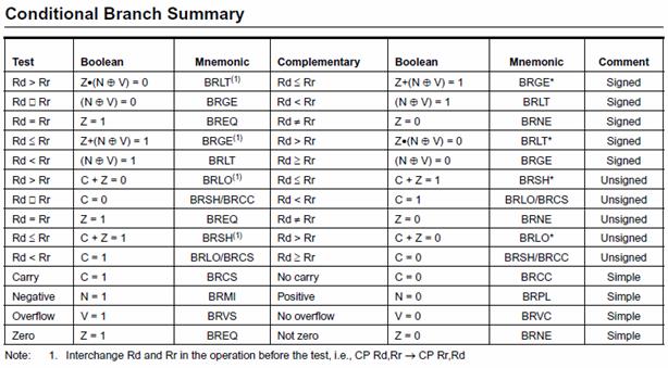
Begin by replacing each decision diamond with a compare bit store (bst) instruction and a brts conditional branch if T flag set instruction. The bst instruction saves the bit to be tested to the T bit in SREG. We then test this bit using the brts instruction. As a general rule use the complementary form of the conditional branch in your decision diamond. For example, if you want to branch if dir bit 1 (dir.1) is clear you would use the brts instruction as shown here.
 lds r16, dir // move direction bit 1 (dir.1)
 bst r16, 1 // into SREG T bit
 brts case1X // your comment here
 bst r16, 0
 brts case01
 ; code to be executed if bit 1 and 0 are zero (case00)
 ; 7 segments gfedcba
 ldi r16, 0b01000000 // spi7SEG = r8, seg_g = 1
 rjmp found

 case01:
 ; code to be executed if bit 1 and 0 = 01
 ; 7 segments gfedcba
 ldi r16, 0b00000010 // spi7SEG = r8, seg_b = 1
 rjmp found

case1X:
; more code and comments...

found:
mov spi7SEG, r16
Programming Option 3: Implement your Truth Table using an Optimized “If-Then-Else” Structure
Compare Immediate (cpi) Instruction
For this solution you will be using the compare immediate instruction to implement the conditional expression in the Table 1.
| Inputs | Outputs | |||||||
| Direction | SW1 | SW0 | dir.1 | dir.0 | Direction Segment ON = 1, OFF = 0 |
|||
| LDg | LDb | LDf | LDa | |||||
| South | DWN | DWN | 0 | 0 | 1 | 0 | 0 | 0 |
| East | DWN | UP | 0 | 1 | 0 | 1 | 0 | 0 |
| West | UP | DWN | 1 | 0 | 0 | 0 | 1 | 0 |
| North | UP | UP | 1 | 1 | 0 | 0 | 0 | 1 |
For this solution each line of the truth table becomes a guess, followed by a compare immediate cpi instruction, and finally a conditional branch instruction.
The Guess
In assembly, it’s all about code optimization. One technique assembly programmers use with conditional expressions to optimize code is to guess an answer and then test for the condition. If the guess was correct then no additional work is required. This typically results in simpler and less confusing code which runs as fast or faster (if the guess was correct) than the more traditional approaches. Here is how our flowchart for seg_b would look applying this technique.
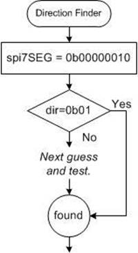
Notice that the code is more linear than the if-then binary tree solution. Here I guess that the return value will be 0b00000010. Specifically, segment seg_b is on with all other segments off. For this to be true, the bear would need to be facing East (dir = 0b01). If my guess is correct then I can jump to my found label. Now lets look at the assembly code needed to implement this flowchart.
Code Example
The code provided here implements the direction finder flowchart defined above. Note: 0b01 assumes that the leading bits are zero and therefore 0b01 = 0b00000001.
 lds r16, dir ; load direction bear is facing into r16
 ; 7 segments gfedcba
 ldi r17, 0b00000010 ; guess bear is facing east (seg_b = 1)
 cpi r16, 0b01 ; if bear is facing east then we are done
 breq found
 ; 7 segments gfedcba
 ldi r17, 0b01000000 ; guess bear is facing south (seg g = 1)
 cpi r16, 0b00 ; if bear is facing south then we are done
 breq found
 ; more code and comments...

found:

mov spi7SEG, r17 ; transfer correct guess to 7 segment register
When comparing the above code with the flowchart one difference you will immediately notice is that the ldi instruction only works with registers r16 to r31 and spi7SEG is in r8, which means we can not directly place our “guess” in r8. Instead I will temporarily place my guess in r17 and only when I reach the found label move r17 (the correct guess) into r8 (spi7SEG).
Programming Option 4: Implement the Arduino C++ Solution in Assembly
This is a design challenge solution, which simply means less instructional information is provided and the solution requires the use of assembly instructions not yet covered in class. Design challenges were created as a response to students who requested more open-ended problem definitions.
Open the Lab02B.ino file within the Arduino IDE. Here the direction segment is chosen by first creating a one-dimensional array of segments (g, b, f, and a). The location of each segment within the array corresponds to the direction the bear is facing. For example, looking at Table 1 above if you are currently facing South (dir = 00), then you want to turn on segment g. Therefore, in the lookup table, the first entry is segment g. Here is the C++ code.
static const byte truth_table[] = {_BV(seg_g), _BV(seg_b),_BV(seg_f),_BV(seg_a)};
 seg7_val |= truth_table[dir_val];
The macro _BV(bit) is defined as 1<<bit.The symbol << being the C left shift operator. In words, the compiler is directed to shift the number 0x01 to the left bit tiresulting a Byte Value (BV) with a 1 in the bit position. For example, _BV(6) would equal 0b01000000. Our assembler does not support the Byte Value (_BV) macro, so we will substitute its definition (1<<bit)
Create the array in assembly using the Define Byte (.DB) assembly directive. Access the array using the indirect addressing mode instruction lpm.
RST_VECT:
 rjmp reset // jump over IVT, tables, and plus INCLUDE code
 .ORG 0x0050 // bypass IVT
 dir_table: .DB 1<<seg_g, 1<<seg_b,="" 1<<seg_f,="" 1<<seg_a<="" em=""></seg_g,>

 .ORG 0x0100 // bypass IVT
 .INCLUDE "spi_shield.inc"
Lab 2 Deliverable(s)
STOP Read the Lab READ ME document contained in the Labs Folder. Be absolutely sure you have followed all instruction in the “Lab Formatting” section of this document. Points will be deducted if you do not follow these instructions. You have been warned.
Make sure your lab notebook is up to date. Follow the guidelines provided in the “Lab Notebook” section of the Lab READ ME document.
Make sure you have read and understand the “Plagiarism” section of the Lab READ ME document, especially if you are repeating the class.
All labs should represent your own work – DO NOT COPY.