Pre-Lab 2: Room Builder and Direction Finder
Table of Contents
Introduction
The Wake-up Machine
Plus Arduino Uno Version
In this prelab you will (1) learn more about the assembler, (2) learn how a 7-segment display works, (3) apply what you learned to display rooms within the maze on the 7-segment display and finally apply what you learned in EE201 “Digital Logic Design” and CECS100 to display the direction the bear is facing using (4) Boolean Expressions and (5) A flowchart.
The Assembler
Seven Segment Display
In this section, you will learn how a 7-segment display works. A 7-segment display is comprised of 7 LEDs labeled a-to-g plus the decimal point (dp).
Each LED segment can be represented as a single LED as shown schematically here with one of the in-line resistors.
When the input (anode) of the LED is connected to a 5v source through a limiting resistor and the output (cathode) is connected to ground, the LED is said to be forward biased. The LED emits light when operating in this mode (ON). If instead we wire the anode of the LED to ground, then no current can flow in the circuit and the LED is said to be reverse biased (OFF).
Traditionally, a 7-segment display is used to form all 10 digits (0-9) by turning on or off the LEDs in different combinations. For example to create the number 1 you would turn on segments b and c.
Part A – Room Builder
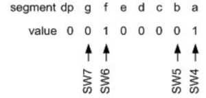
In the first half of the lab, instead of numbers we will be using our 4 switches and the 7-segment display to draw the 24 = 16 different rooms that our bear may encounter in any maze. As an example, let’s use our four switches to draw a room with a north and west facing wall. For this room we would turn on (up position) switches 6 and 4, leaving switches 7 and 5 in the off position (down). The resulting room configuration is shown in Figure 2.
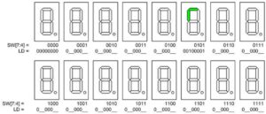
Here are the sixteen possible situations or “rooms” our bear may find as he explores the maze. The decimal point dp and segments c, d, and e are always “off.” Segments a, b, g, and f are turned “on” and “off” to show the room configuration. Working from Figure 2, complete the drawing below by filling in the LED pin values and coloring in the LEDs that are turned “on” for each switch SW[7:4] combination. I have included a file named Room_Combination.JPG here for you to use.
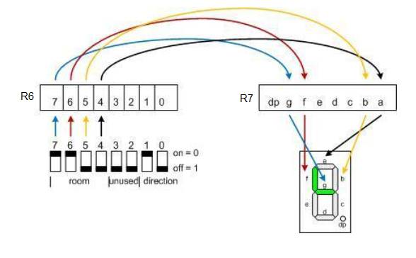
After completing the drawing above you may have noticed that the following relationships exist between our switches SW[7:4], returned in register r6 by ReadSwitches, and the 7-segment LEDs, sent in register r7 as an argument to WriteDisplay. Figures 4 “MazeRoom” graphically shows how your program will work.
In the previous lab you connected your eight (8) switches to the 7-segment display by using the mov instruction. In essence you created a “software” wire between register 6 bit 0 and register 7 bit 0, register 6 bit 1 and register 7 bit 1, etc. As seen from a quick look at the crossing lines in Figure 4, this solution will unfortunately not work for your room builder code. Instead you will use two new bit instructions. The “Bit Store from Bit in Register to T Flag in SREG” (bst Rd, b) and the Bit Load from T Flag in SREG to Bit in Register” (bld Rd, b) instructions. Here is how these two bit instructions would be used to create the blue “software wire” between register 6 bit 7 and register 7 bit 6 (seven segment display segment G).
call ReadSwitches
bst r6,7 // wire switch 7 to segment g (south wall)
bld r7,6
call WriteDisplay
As shown in Figure 4, the call to ReadSwitches places the state of the eight (8) switches on the proto-shield into register r6 and the call to WriteDisplay copies the bits in register 7 to the 74HC595 8-bit Shift Register IC wired to the 7-segment display (see proto-shield schematic). The two lines bst and bld therefore functionally wire switch 7 to segment g. Let’s take a closer look.
Turn to “Appendix C ATMEGA328P Assembly Instructions” in your textbook and specifically Table C.4: “Bit and Bit-Test Instructions” or the free 8-bit AVR Instruction Set document 0856 available from Atmel, you can find it here.
The bst “Bit Store from Register to T” instruction copies bit 7 from register 6 into the T flag bit located in the status register (SREG) of the AVR processor. You can think of T as our general purpose 1-bit register. As most 8-bit data uses one of our 32 general purpose, single bits of data use the T bit. The bld “Bit load from T to Register” completes our “software” wire by sending the contents of the T bit to register 8 bit 6.
Working from the above example you should be able to write the next six assembly instructions to wire switches 6, 5 and 4 to 7-segment LEDs f (west wall), b (east wall) and a (north wall) respectively.
call readSwitches
bst r6,7 // wire switch 7 to segment g (south wall)
bld r7,6
… your code goes here
call writeDisplay
Part B – Direction Finder
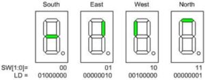
In the second half of the lab you will be using two (2) more switches and the same 7-segment display to show the direction you want your bear to walk. For example, if your bear is heading north, and enters a room requiring a right-hand turn (see Figure 5), then you would turn on segment b indicating that the bear should go East.
For this lab, we will use Switches 1 and 0 on the development board to input the direction we want the bear to go. These switches correspond to port pins PINC.1 and PINC.0 respectively. As before, we will assume that these port pins have been input to register r6 as illustrated in the arduino-proto-shield schematic. The logic value corresponding to each switch position is defined by variables dir.1 and dir.0. The following table translates these two switch positions into their corresponding dir input values and outputs signals to LED segments f, a, b, and g of the 7-segment display.
| Inputs | Outputs | |||||||
| Direction | SW1 | SW0 | dir.1 | dir.0 | Direction Segment ON = 1, OFF = 0 |
|||
| LDg | LDb | LDf | LDa | |||||
| South | DWN | DWN | 0 | 0 | 1 | 0 | 0 | 0 |
| East | DWN | UP | 0 | 1 | 0 | 1 | 0 | 0 |
| West | UP | DWN | 1 | 0 | 0 | 0 | 1 | 0 |
| North | UP | UP | 1 | 1 | 0 | 0 | 0 | 1 |
Continuing with our initial example; we have a bear in a room with north and west facing walls (SW[7:4] = 0101), we want the bear to go east (SW[1:0] = 01). For this situation the switches would be set as shown in the illustration below.
Now that we know what we want we will look at two different ways to implement it using our microcontroller.
Boolean Logic
Applying what you learned in your Digital Logic Design class, construct a sum-of-products (SOP) expression for each direction segment. For our example, we would want to light the direction segment pointing east. All work should be included in your lab notebook.
To draw the Boolean equations in Microsoft Word select Insert – Equation …
Flowchart
In the last section, you applied what you learned in EE201 “Digital Logic Design” to create your Boolean equations to calculate the segment to be turned ON. In this section, you will apply what you learned in your programming class and in pre-lab 1, to construct a flowchart to determine which segment to turn on based on dir bit 1 and bit 0. Specifically, you will translate the flowchart into a series of conditional statements. For example, if dir bit 1 is equal to 0 and dir bit 0 is equal to 1 then turn on bit 1 of register r8. From the introduction to this section (Direction Finder) we know this will turn on segment b (i.e., spi7SEG = 0b00000010).
Draw your flowchart using your favorite drawing program (Visio, Illustrator, etc.).
Part C – Questions
- A student flips the switches on their proto-shield, such that, switches 7, 2, and 0 are up, and the rest are down, as represented by the following blocks:

The student then runs ReadSwitches and executes the following assembly code:
clr r7
bst r6, 2
bld r7, 5
bld r7, 3
bst r6, 4
bld r7, 7
a. What is the binary value of register 6 (r6)?
b. What is the binary value of register 7 (r7)?
c. What is the value of the T bit in SREG? - The eighth bit of register 17 (bit # 7) needs to be moved into the fourth bit of register 18 (bit # 3).
a. Write two lines of code to achieve this task using bst and bld.
b. If the starting hexadecimal value of r17 is 0x7A, and the starting hexadecimal value of r18 is 0xEC, what will be the final hexadecimal value of r18 after performing your code? - A student is debugging their code for the proto-shield, and has tried to simulate a switch input as in problem 1. She has checked the following pins in the AVR simulator:


When she runs ReadSwitches, register 6 (R06) and the watch window for “switch” contain a hex value of 0x80.
a. Why does register 6 contain 0x80 and not 0x85?
b. Show how the student should have clicked the pins in AVR simulator:


What Should I Turn In?
Turn in the following material. The page numbers may change if you need more room for certain parts but the order must be followed. Points will be deducted if this instruction is not followed. Make sure all your original work is in your Lab Notebook. All written material must be typed or neatly done in ink. Once again please do not copy.
Page
- Title page with the pre-lab number, your name and picture, today’s date, and the day your lab meets.
- A completed version of the Figure 3 “Room Combinations” picture.
- Your assembly code from “Part 1 – Room Builder” Your code must be typed, but does not need to be assembled.
- Four (4) Boolean Expressions for the four direction segments
- A Flowchart of Direction Builder
- Questions and answers to all questions.


