Microcontroller Based Interface Design
Part 1
System Engineering Your Robot
Table of Contents
Introduction
In this post I am going to talk about the 3DoT Microcontroller Board and its integration with peripheral devices including sensors, actuators, and serial communications. A basic knowledge of programming in C++ is assumed.
Microcontroller Based Interface Design
Embedded Systems
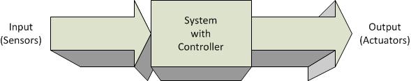
Figure 1. Controller-Based System
Engineers design systems. A system can be characterized by a box with an input and output. Typically the engineer is tasked to design the box with a given set of inputs and the desired output.
- When a controller “the brain” is part of the design solution, the design is known as an Embedded System.
- The controller may be implemented using an ASIC (Application Integrated Circuit), FPGA (Field Programmable Gate Array), or in most cases a Microcontroller. A combination of the above on a single IC, is known as a System on a Chip (SoC).
- For this discussion, the input device is by definition a Sensor, and the output device an Actuator.
In this post we look at the microcontroller based system design used by our robots. It is hoped that by looking at this specific example you will be able to apply the lessons learned to the design of other microcontroller-based systems.
Robot Microcontroller Based System Design
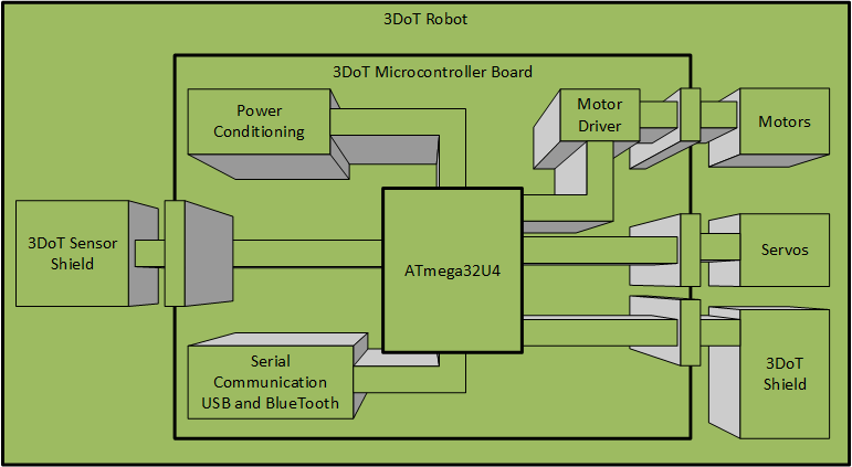
Figure 2. 3DoT Microcontroller Based System
Figure 2.0 illustrates our robot design from a generic capabilities perspective. At the heart of our embedded system is an ATmega32U4 Microcontroller.
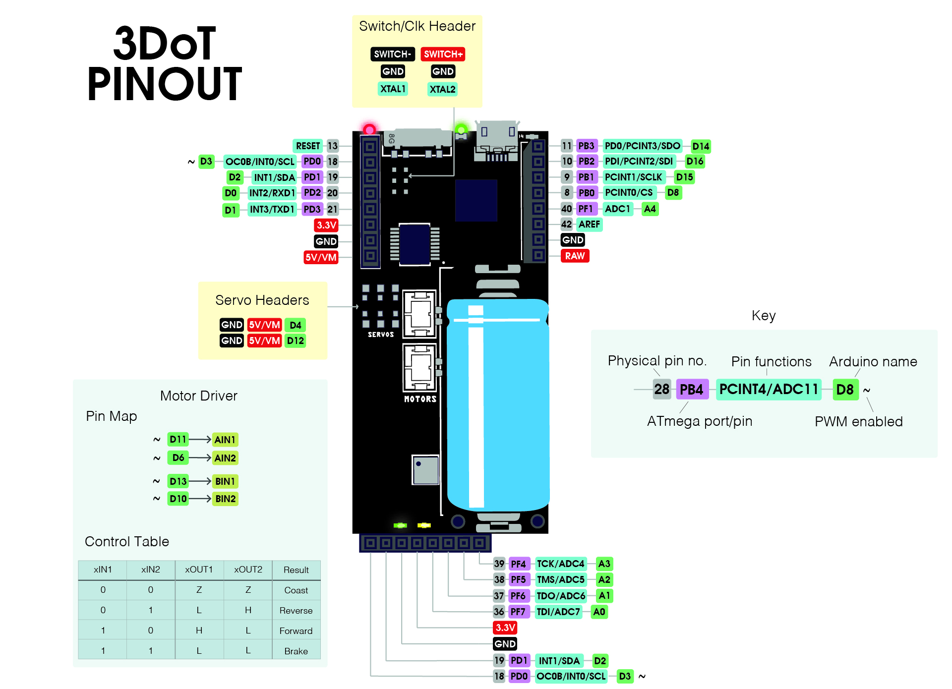
The ATmega32U4 is built into the Arduino compatible 3DoT (3D of Things) Board. Let’s take a closer look at the hardware and software built into the 3DoT board.

Figure 3. 3DoT Board
Hardware
The 3DoT board is a micro-footprint 3.5 x 7 cm all-in-one Arduino compatible microcontroller board, that integrates all the components needed to create a small autonomous, RC controlled, or telepresent robot.
- Microcontroller: At the heart of the 3DoT board is an Arduino Leonardo based microcontroller unit (ATmega32U4), featuring an 8 MIPS (Millions of Instructions Per Second) 2-stage pipelined AVR RISC processor.
- USB (Universal Serial Bus) serial communications circuitry allows you to upload your programs and download data.
- An FCC-certified BLE 5.0 module (optional) allows wireless communication with the ArxRobot Android/iPhone App and Arxterra control panel.
- Power Management: Power for the 3DoT board is provided by an RCR123A LiPo 650 mAh rechargeable battery with associated power protection, switching, and conditioning circuitry (3.3v and 5v). Plus, an integrated 3.7v Li-ion battery charger with battery level sensor circuit. You also have access to an external battery connector – for input voltages between 4 – 18 V.
- Motors & Servos: To control your robot’s motors the 3DoT board includes a DRV8848 Dual Motor Driver. JST Connectors are provided for up to two (2) DC Motors and two (2) Micro or Ultra-Micro Servos.
- Expansion: Customize your robot with 8-pin forward sensor and 16-pin 3DoT Shields, also known as daughter boards.
- 16-pin top female headers for shields – providing I/O, I²C, SPI, USART, 3.3 V and 5 V.
- The forward-facing 8-pin female header for sensor shields – providing 4 analog pins, I²C, and 3.3 V power – for sensor shields like infrared or metal-detecting shields. Great location for headlights, lasers, ultrasonics, etc.
- Programming switch: Three-position switch for easy programming
- No more double-tapping a button and rushing to program your board, or your robot trying to drive away while programming. Set the switch to PRG to program, RUN to execute your code.
Software
- Programs are written in the Arduino IDE (Integrated Development Environment).
- Pre-installed Arxterra 3DoT bootloader plus Robot3DoTBoard library – fully customizable for your robot
- Together this software suite running on the ATmega 32U4 microcontroller allows you to control a 2-wheel robot out-of-the-box using the FREE ArxRobot Android/iPhone App.
- If the robot can hold your phone, then you can remotely control your robot from anywhere with an internet connection from the Arxterra Control Panel.
Document Objective
The objective of this document is to teach you how to interface peripheral devices to a microcontroller based system. We first…
- Allocating the resource of our MCU (Micro-Controller Unit).
- Look at how sensors and actuators could be incorporated into this design
- Present the reference design as an example.
Allocating MCU Resources
Our embedded system is comprised of a 3DoT Microcontroller Board. At the heart of the system is the ATmega32U4 microcontroller. The 3DoT board consumes some of the resources of the ATmega32U4 in exchange for extending the capabilities of the integrated system. Table 1 provides a mapping of these resources and ultimately the interface resources available to the sensors and actuators of your robot in columns G through K. Columns L and M show how the 16-pin 3DoT and 8-pin sensor headers can be used to add an IR sensor and wheel encoder shields.
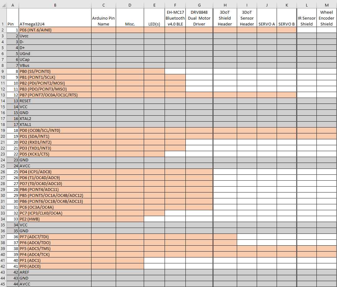
Table 1. Interface Matrix
ATmega32U4 I/O pins (columns A and B)
The ATmega32U4 comes in a 44-pin QFN (Quad Flat No-leads) and a TQFP (Thin Quad Flat Package). The arrangement of these pins around the QFN or TQFP IC is shown in Figure 3.0. Each pin is assigned both a number and a name.
Due to pin-out limitations of the IC package (QFN and TQFP), most I/O pins of the ATmega32U4 are multiplexed. Specifically, they can be programmed to provide different interfaces to the system. For example, pin 41 PF0 (ADC0) can be wired to a digital I/O device like a button or and LED. Conversely it could be wired to an analog input to measure a voltage output by an IR sensor.
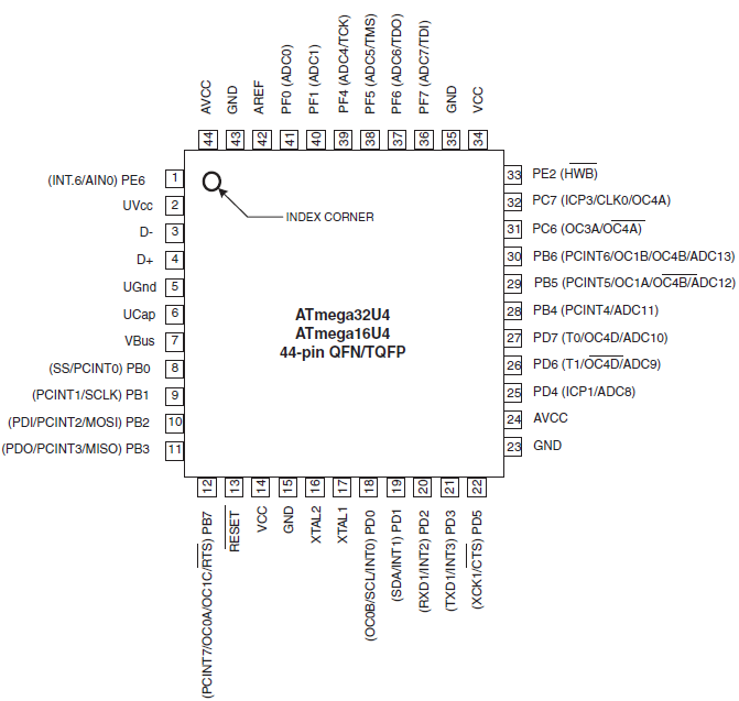
Figure 3.0 ATmega32U4 Pin-out
Table 3.0 allows us to place the ATmega32U4 within the context of our design. Specifically, how are we going to wire up all the actuators and sensors to our microcontroller IC. We begin by adding each pin number and its name to columns 1 and 2 respectively.
As shown in Table 3.0 most but not all rows may be assigned as I/O pins. For example the VCC, GND, USB, XTAL (crystal) and reset pins are not available. These non-I/O pins appear as Gray rows in the table. What this means to the system designer instead of having 44 Multiplexed I/O pins you now only has twenty twenty-six (26). All 26 of these multiplexed pins may be used as digital I/O pins (PB7-0,PC7-6,PD7-0,PE6 and PE2, PF7-4 and PF1-0). These I/O pins appear as Orange rows in the table. When one of these I/O pins is consumed, the remainder of the row is White.
Arduino I/O Pins (column C)
The Arduino was designed as a tool for introducing students to embedded systems. To a student unfamiliar with peripheral subsystems like GPIO (General Purpose Input Output) ports and an ADC (Analog to Digital Converter), the names assigned to the pins of the ATmega32U4 can be intimidating. Instead, the creators of the Arduino realized that these complex electronic systems could be introduced in a step-by-step fashion by starting with the function to be performed. Put another way, students new to engineering are more interested in “what” the pin can do, rather than “how” it does it. For this reason, the Arduino creators renamed the pins by function. For example, pins that work with digital binary inputs and outputs start with the letter D and are numbered sequentially (D0 to D23). Pins that work with Analog inputs start with the letter A and are again numbered sequentially (A0 – A10). Along with these “functional” names came simple program instructions, like digitalRead(D0) and digitalWrite(D1) for digital signals and analogRead(A0) for analog inputs.
The 3DoT instruction set builds on this functional vs. technical philosophy by allowing you to control your robot’s movements with a single move() instruction.
Table 1.0 Column C shows the Arduino names assigned to each ATmega32U4 I/O pin (orange rows). Specifically, digital pins D0 to D23 and analog inputs A0 to A11. The single exception is pin 33 PE2 (HWB) which is set to 0 (wired to ground) for Arduino ATmega32U4 microcontroller boards. The 3DoT board wires this pin to its ON/PROG/RUN switch. This change was made to make the 3DoT board easier to program than its Arduino cousins.
3DoT
To build an Arduino-based telerobotic Robot, in addition to the microcontroller board you would need a battery, charger, Bluetooth shield, motor shield, and a breadboard containing miscellaneous parts. The 3DoT board integrates all these components on a single 3.5 cm x 7 cm board. As a part of your robot, all these built-in functions consume microcontroller pin resources as defined in columns D, E, and F. In most instances, once used these resources are no longer available to implement other functions.
DRV8848 Motor Driver (column F)
Figure 3.1 shows how the DRV8848 Dual Motor Driver is wired to a typical MCU. Looking at Table 3.0 column F we see that our motor driver is wired to pins pin 25 to 31 of the ATmega32U4 MCU. Also notice that after this column these rows are colored white indicating that the resources are no longer available to the system.
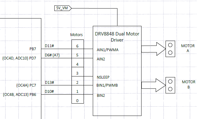
Figure 5. ATmega32U4 to DRV8848
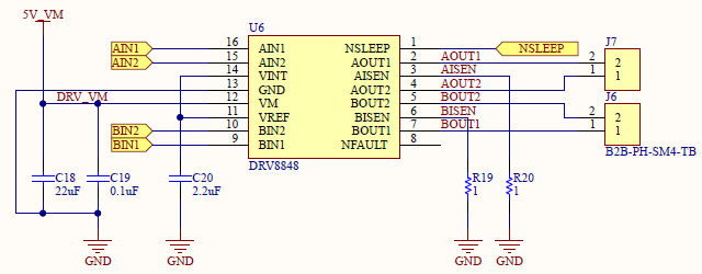
Figure 5. 3DoT DRV8848 wiring
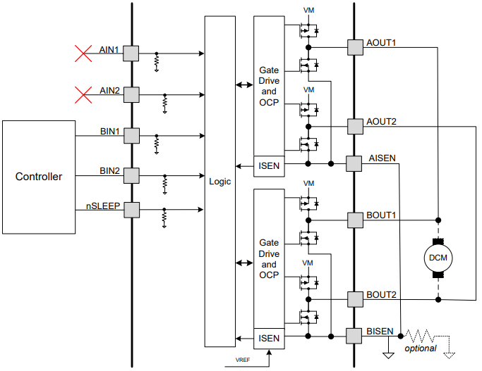
Figure 4. Dual Motor Driver
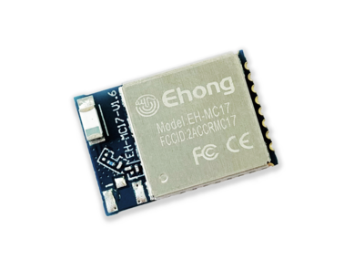
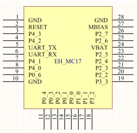
EH-MC17 Bluetooth Module (column E)
The EH-MC17 (Figure 7) sends and receives data to the USART peripheral subsystem of the MCU. The USART serial interface only needs 2 wires (RX and TX) to physically implement this interface. As shown in column B of Table 3.0 the TX1 and RX1 pins are internally routed from the USART peripheral subsystem to pins 20 and 21 of the ATmega32U4 IC. A few additional things are of note here.
- To add this Bluetooth module we need to sacrifice Arduino digital pins D0 and D1.
- Unlike the motor driver, these two rows do not immediately show these pin resources as being consumed. Specifically, they are brought out to the 3DoT Shield Header J1 (column G). The reason is simple. The addition of the HM-11 module to the 3DoT board is optional. If the robot designer chooses to not solder the HM-11 module to the bottom of the 3DoT board, then they are free to use these pins to implement a different serial communication standard (e.g. XBee, WiFi) or for a fully autonomous robot, Arduino digital pins Do and D1 are again available.
- It is curious to note that the MCU d0/RX1 pin is wired to the HM-11 TX pin and that the MCU d1/TX1 pin is wired to the HM-11 RX pin. Confusing isn’t it and also a very common wiring error. You can think of it this way; one person’s output is another person’s input.
LEDs, Switch, and Battery Level Circuit (column D)
Beyond the Motor Driver (Table 3.0 column F) and the HM-11 Bluetooth module (Table 3.0 column E) the 3DoT Board uses a few additional MCU pin resources for LEDs (Light Emitting Diodes), the ON/PROG/OFF Switch, and the Battery Level circuit. Let’s take a closer look at column D of Figure 3.0.
LEDs
RX LED 4 and TX LED 6 are wired to pin 8 (Arduino pin D17/RXLED) and pin 22 (Arduino pin TXLED). The famous Arduino on-board LED typically uses by the BLINK script, is wired to pin Port D bit 5, not Arduino digital pin 13.
DP3T OFF/PROG/RUN Switch
The Arduino Leonardo and in fact all Arduino 32U4 based boards have a peculiar problem as a result of the ATmega32U4 incorporating the USB peripheral system as part of the MCU. On “traditional” Arduino boards, like the UNO, a separate ATmega MCU is dedicated to implementing the USB interface. As a result, ATmega32U4 based Arduinos must juggle between the user uploading programs and acting as a USB port for the user’s program. You need the first function when you are programming and the second if you want your program to interface to the computer. For example, if you want your program to output to the Arduino IDE’s Serial Monitor. The Arduino developers solved this problem by having the Arduino upon reset look for the user to upload a program and after a few seconds, if the user does not start the upload process then it switches to running the currently loaded program. In many cases, the user can not initiate this upload process fast enough for the Arduino’s liking resulting in the “double-tap” solution which only works part of the time. To solve this problem 3DoT developers implemented a different solution. The 3DoT board has a DP3T (Double Pole Triple Throw) Switch. As the name implies this switch has three positions (OFF/PROG/RUN). Now the ATmega32U4 bootloader, by interrogating pin Pin 33 PE2 (HWB), can directly determine if you want to upload a program (PROG) to the ATmega32U4 or RUN your program.
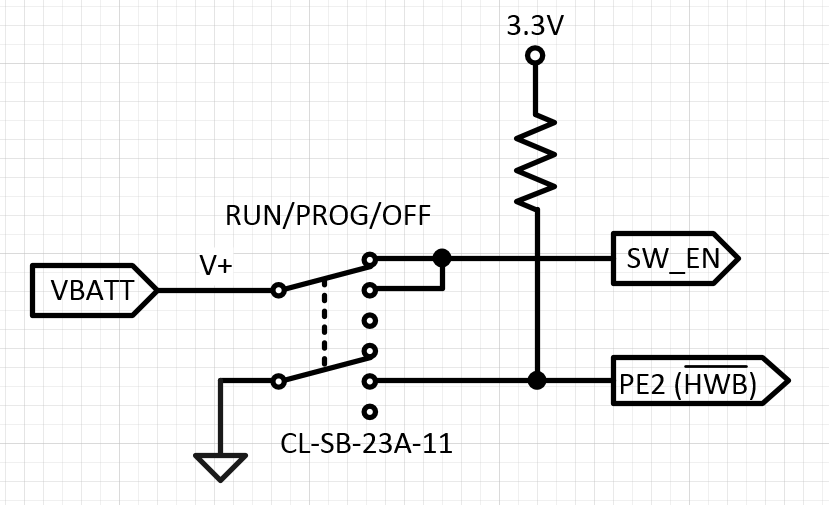
Figure 3.4 DP3T Switch
Battery Level Circuit
Going back to Table 3.0 column D row/pin 41 we see VBATT_LVL. Which is short for “Voltage Battery Level.” As the name implies the function of this pin is to read the current battery voltage. A simple voltage divider is all it takes to implement the battery level circuit, with the top of the voltage divider wired to the positive lead of the battery and the center of the divider wired to pin 41. The output of this circuit is an analog voltage typically between 2.1 and 1.2 volts. Going back to pin 41 we see that the ATmega32U4 names this pin PF0 (ADC0), while the Arduino names the pin A5/D23. The key here is that the pin can be both an analog input or digital input or output. So to implement this function, we will be using the Analog to Digital (ADC) peripheral subsystem of the ATmega32U4 and not the General Purpose I/O (GPIO) port used for digital inputs and outputs.
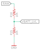
Figure 3.5 Battery Voltage Level Circuit
Robot
In this section we are going to look at the MCU resources available for customizing your robot. As already mentioned the 3DoT board directly supports a robot with two (2) DC motors and two (2) micro-servos. The DC motors are controlled by the TB6612FNG motor driver IC whose pins have already been allocated. The micro-servos have their own dedicated connector J7 (Figure 4.1), and wire directly to the ATmega32U4 through limiting resistors. The limiting resistors protect the MCU from damage in the event of an accidental short for the V7 boards.
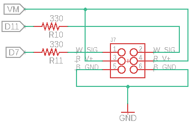
Figure 4.1 Servo Connector J7
Customization of your robot is afforded by three 8-pin connectors J1, J2, and J3. Daughter boards that plug into connectors J1 and J2 will be called “3DoT Shields.” Daughter boards that plug into connector J3 will be called “3DoT Sensor Shields.”
3DoT Shields
Connectors J1 and J2 are located on the top of the board in a fashion similar to the Arduino UNO, and like the UNO can support one or more stackable 3DoT Shields. This is especially true of the 3DoT board, whose J1 and J2 connectors support three (3) different serial communication protocols: I2C, SPI, and USART. To take this to the extreme, you could theoretically stack 127 I2C shields without even mentioning SPI and USART shields. In addition, the J2 pins 5 and 6 support one (1) Analog signal with an associated reference voltage (AREF). To avoid conflicts with 3DoT Sensor Shield (connectors J3) on the bottom of the board, do not wire digital I/O to I2C pins SDA and SDL (D2, D3). In addition, if your robot comes with the HM-11 Bluetooth module do not wire digital I/O to USART pins RX and TX (D0, D1).
As we have seen, the multiplexing of the I/O pins immediately forces the system engineer to make trade-offs in the design of their shields. For example, If your making a fully autonomous robot (no HM-11 Bluetooth module), you do not need the single analog input A4 on connector J2, and are your forward 3DoT sensor shield is not using I2C pins SDA and SCL, then your 3DoT Shield could have a maximum of nine (9) digital I/O signals. In most designs all those conditions will not be met, and you will have to trade-off one MCU peripheral subsystem (see Figure 4.2) against another (GPIO Port, A/D Converter, I2C, SPI, and USART).
3DoT Sensor Shields
Connector J3 is an 8-pin connector located on the front bottom of the board. This connector is designed for “sensor shields” located on the front of the robot. Typical applications would include line following robots. With sensors in mind, the connector includes four analog inputs (A0 to A3) and support for the I2C serial communication protocol (SCL, SDA). For sensor shields requiring digital I/O lines it is recommended that one or more of the analog pins (D18 to D21) be utilized. As mentioned in the previous paragraph, to avoid conflicts with 3DoT Shields (connectors J1 and J2) on the top of the board, do not wire digital I/O to the I2C pins (D2, D3).
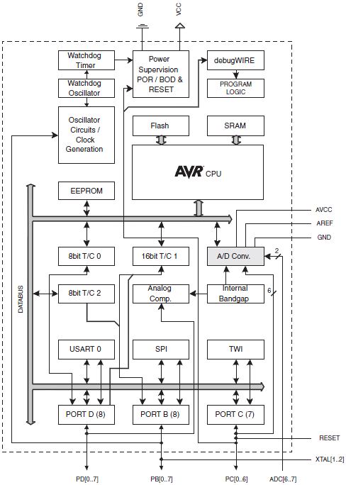
Figure 4.2 ATmega328P Block Diagram
| In the future when I talk about Arduino peripheral subsystems, as I did in the previous paragraph, I will show the ATmega328P Block Diagram in place of the ATmega32U4 processor used on the 3DoT board. The ATmega328P microcontroller was used on the original Arduino UNO and is far simpler than the ATmega32U4. Therefore, I can make the same points using the ATmega328P, without adding unnecessary complexity to the topic under discussion. |
Next Step
Applying what you learned here, in “Microcontroller Based Interface” Design Part 2 we will look at how sensors and actuators can be incorporated into your robot.