C++ Robot Prelab 1 – Line Follower
Table of Contents
Understanding the Major Parts of the Maze Solving Robot
In the previous lab, you spent time learning about infrared sensors and how they could be utilized to detect the lines on the maze. The optimal distance, LED current, and resistor values were found for the different materials that the maze could be made from. In this prelab, you will be focusing on how the robot is going to traverse the maze with its DC motors and the corresponding circuitry needed.
How A DC Motor Works
There are many types of motors and they have varying specifications for their applications such as generating power or moving a wheel. We are focusing on the DC motor for our robots.
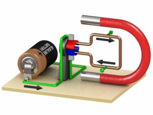
The basic theory behind how these motors work is to make use of varying electromagnetic fields in order to cause rotation. The exact names of parts and the theory is covered in further detail in EE 350 and is not required for our class. A simplistic interpretation is shown in figure 1.
From the figure, you will notice four main parts. These are the permanent magnet, rotating metal, contacts to the power source, and the power source itself. The permanent magnet is used to provide the constant magnetic field that will influence the piece of metal when current is flowing through it. Depending on the direction and amount of current flowing, a varying electromagnetic field will be generated and the interaction with the constant magnetic field will cause a force to turn the piece of metal. The contacts are designed in such a way that as the metal rotates, the direction of the current will switch so that the rotation will continue.
The constant changing of the electromagnetic field allows for the motor to gain speed. In order to reverse the direction, you would need to change the polarity of the voltage being applied to the piece of metal. This entire setup has been refined and miniaturized to the current form of motors that you see today.
Different Parameters To Consider
Now that we have covered the theory behind how DC motors work, we are going to focus on the major parameters to evaluate when choosing the right part for your robot. Some common parameters are the size of the motor, shape of the motor, revolutions per minute (RPM), operating voltage, stall current, and price. There are several other things to consider such as manufacturer, materials used, or gear ratios and the list goes on.
There are several parameters that you may never have encountered before, so we will go over some of them here. The first set that we will focus on is related to the strength of the DC motor. The torque of the motor tells us how much force is generated by the rotating shaft. This is one of the most crucial values to consider because it dictates what the motor is capable of moving. If the load (whether it is a wheel or some mass to move) requires a higher torque than the motor can provide, nothing will move and the motor could be destroyed. The torque may not always be given on the datasheet, so we will need to use other commonly given values such as the revolutions per minute (RPM) in order to solve for it. Certain motors have gears attached to the shaft in order to provide higher torque outputs, which is where the gear ratio parameter comes into play. This is what allows motors that operate at lower voltages to generate a high amount of torque and gives many options.
The second set is related to the power consumed by the motor. You will find several parameters referring to unloaded, loaded, or stall conditions. These values are important for determining if your power supply can provide enough current to the motors and other peripherals on your robot. The unloaded condition refers to when the motor shaft is freely rotating with nothing attached. This will generally never be used because our robots will be operating with a load. Finding a datasheet with the loaded condition will be very rare because the results vary depending on the load itself. You will commonly find the stall condition instead. This occurs when the motor is unable to move the load itself and is using full power to try to move it. This state is dangerous because it could damage the motor if it is kept in the stall condition for too long. It will also indicate the highest current consumption possible for your motor. When selecting the parts for the robot, this is one of the most important things to keep in mind because in the case your robot gets stuck on something, you do not want it to stall and completely drain your battery.
Question 1 – Which of the following parameters are the most important to consider when choosing the correct motor for your robot?
The operating voltage, the size of the motor, the manufacturer, the unloaded current, the gear ratio, or the stall current
Question 2 – What are the specifications for the motor suggested for the Sparkfun robot? (This is referring to the Hobby Gearmotor that was linked on the list of materials.) Please indicate the operating voltage, torque, revolutions per minute, and stall current.
H-Bridges
Now that you have a better understanding of how DC motors operate, we will focus on how they are controlled and implemented on small robots. The motor shaft is made to rotate by applying a voltage to the motor and the direction that it spins is controlled by the direction that the current flows. Any sudden switches to the power being supplied can cause damage to the components, so circuitry is needed to protect the motor when the direction is changed. This is where H-bridges come in. They are always used with DC motors in order to simplify the process of controlling them and allow for the motors to be powered separately from the microcontroller.
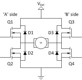
Figure 2 shows the typical H-bridge which is made up of four transistors and four diodes. The configuration is set up this way so that current can only flow in one of two directions depending on the transistors that are turned on.
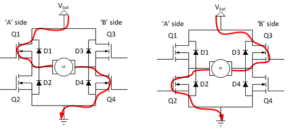
As indicated in Figure 3, current will flow from Vbat to ground if Q1 and Q4 are conducting. That will cause the motor to rotate in one direction. If Q2 and Q3 are turned on, current will flow in the opposite direction and make the motor change its rotation. Because of what they are used for, H-bridges are more commonly known as motor drivers.
Question 3 – What is the name of the suggested motor driver that was listed for the Sparkfun robot? How many control signals does this motor driver have?
GPIO Ports and Configuring the Pins
In lecture, you have been taught about the available input and output pins that can be configured for different applications. We will be focusing on implementing that configuration in Lab 1 and develop the code for the Sparkfun robot. In order to prepare for that, practice answering the following questions.
Question 4 – What is the Arduino equivalent for pin that is connected to PWMA on the TB6612FNG motor driver? This is referring to pin PD7 on the Atmega 32U4. (What is the term that you would use in the Arduino IDE for this pin?)
Question 5 – In order to configure pins to be outputs, the bit corresponding to that pin in the DDRX register needs to be set to 1. What is the expression that will configure pins PB6, PB3, and PB0 as outputs?
Image Sources
Figure 1 – https://nationalmaglab.org/education/magnet-academy/watch-play/interactive/dc-motor
Figure 2 – http://www.modularcircuits.com/blog/articles/h-bridge-secrets/h-bridges-the-basics/
Figure 3 – https://www.quora.com/What-is-the-working-of-a-H-bridge-circuit


