Electronics and Control: Software Design
By Chelsea Mediavilla (Electronics and Control)
I discuss the software design for the two main electronics on the CubeSat. The Arduino code controlling both components is explained and provided.
Table of Contents
Introduction
The software design for this project has two main functions: reading the Geiger tube and communicating with the µCAM-II (micro camera). Use of the Geiger tube requires a code to receive the impulses sent from the BJT circuit attached to the end of the tube. The camera requires code capable of sending and receiving commands outlined in the µCAM datasheet through a universal asynchronous receiver and transmitter (UART) port. Both devices were coded using the Arduino IDE.
The Geiger-Müller Tube
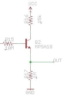
This form of dosimeter counts the number of radiative events occurring in an area. The Geiger-Müller tube has a window located at the end of the tube that is sensitive to ionizing particles. When ionizing particles (alpha, beta, or gamma) hit the window, particles within the tube begin to ionize creating an avalanche of ionizing particles. The avalanche causes a rush of electrons that send a pulse of current through the end of the tube where it is read by a sensing circuit. For our project this circuit is a high voltage bipolar transistor, MPSA-18, as used in the SparkFun Geiger board. This circuit outputs a reduced voltage to be read by the microcontroller.
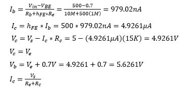
Assuming that 500 volts is read at the anode of the Geiger tube, the output voltage can be found using the BJT datasheet and the following calculations:
Based on the schematic for the SparkFun Geiger Counter board, the output of the BJT was connected to an external interrupt on the microcontroller. This allows for continuous updates when new radioactive events occur. I created an interrupt on external interrupt 0 on the microcontroller. Any changes in value (high to low or low to high) triggers the interrupt where the value of the pin is analyzed. Because the external interrupt is read as an input, the voltage of the pin is considered HIGH when it exceeds 3 volts. When zero current is being sent through the BJT, the output voltage is zero. When 500 volts is sent to the through the BJT will produce an output of about 4.92 volts, thus making the microcontroller HIGH. When the external interrupt detects a HIGH signal, the number of counts is incremented. A “for” loop keeps track of the time the system is running and displays the number of counts at set intervals of time.
µCAM-II
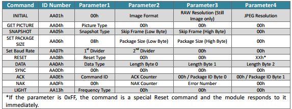
As previously discussed in the Single Event Upset Blog, the µCAM-II, requires a set of commands to be sent and received by the microcontroller. The code I used to do this was found on GitHub, and edited to match the needs of our particular project. The code initially sets the micro camera to communicate with a microcontroller through the MCU’s built in UART ports, RX and TX. On the ATmega32u4, these hardware serial pins, are labeled as “Serial1”. The “Serial” UART connection is reserved for devices connected via USB; for example, the Arduino IDE serial monitor. Our final project does not communicate through a USB port, and thus does not use the “Serial” port. The “Serial1” port, however, needed be set aside for RS-422 implementation. This meant that the code had to be altered to communicate data on a new set of pins.
Arduino has a built in SoftwareSerial library that allows users to create serial ports on any digital pins that support change interrupts. The ATmega32u4 is limited in the number of software serial ports that can be used because few of its digital pins support change interrupts. Among those that do support them, are the MOSI and MISO pins (pins 16 and 14). The original code uses a built in C++ library to call and execute functions, however, this library uses the built in “Serial1” port. In order to read off of the MOSI and MISO pins, I copied the entire library to an ino file and edited out C++ specific functions such as the “this->” command. After rewriting the code to transmit data through the new port, I added loops into the code to ensure reception of data. The micro camera automatically adjusts to baud rates between 9600 bps and 921600bps. Unfortunately, software serial ports are much slower than hardware ones. In order to receive the complete picture data, I adjusted the code so that after the initial connection is set at 9600bps, the baud rate of the camera is reset to 4800bps. At this baud rate JPEG images can be processed, however, RAW images data is too long, and thus a much slower rate is needed. Total sync and receipt of an image takes about 30 seconds, then repeats. In the future, the camera should be connected through the hardware UART port in order to achieve faster transmission. If a second high-speed UART connection is necessary (for examples RS-422), then a microcontroller with multiple hardware UART ports would be ideal.
Conclusion
The software design for the Spring 2016 SPARCCS project requires coding for the micro camera and the Geiger- Müller tube. The Geiger tube is connected to a BJT circuit where a pulse is sent to the microcontroller. The MCU sums the external interrupts to display the total radioactive events occurring in a period of time. The micro camera is set to initially sync at 9600bps then slow to a more manageable 4800bps in order to receive data. The code for both devices loops continuously.
References
SparkFun board: https://www.sparkfun.com/products/11345
MPSA 18 datasheet: http://www.redrok.com/NPN_MPSA18_45V_100mA_0.625W_Hfe400_TO-92.pdf
µCam datasheet: http://www.mouser.com/ds/2/451/uCAM-II_datasheet_R_1_0-472661.pdf


