FINALIZED INTERFACE MATRIX & DEFINTIONS
By Railly Mateo (Systems Engineer)
Approved by Paul Oo (Project Manager)
Approved by Railly Mateo (Systems Engineer)

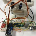
Table 1 above show the 1st portion of project’s updated system interface definitions. The left side of the table has information on our subsystem components, while the right side is simply the microcontroller (Arduino Micro). Each component is then defined by its pinout data (pin number and pin symbol), which is then used as information for the microcontroller’s pinout.

Table 2 above show the 2nd portion of project’s updated system interface definitions. Unlike the first table, this section focuses only on our servo interface. The left side of the table has information on the servo driver, while the right side is simply 6 µservos. Because the servo driver has no numbered pins, the table separates each section of the servo driver by its basic connections (PWM, V+, & GND). The µservos are then connected to these connections through their PWM, V+, & GND wires.
A full system block diagram explains how these subsystems structurally connect.
The wiring diagram post explains how we planned to eliminate any possibility of branch-like wiring.
