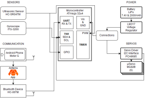
Fall 2015 MicroBiPed System Block Diagram Update
FINALIZED SYSTEM BLOCK DIAGRAM
By Railly Mateo (Systems Engineer)
Approved by Paul Oo (Project Manager)
Approved by Railly Mateo (Systems Engineer)
The block diagram above shows the updated block diagram for BiRex. The blocks are positioned based on their subsystem information. This post will give brief descriptions to explain each section of the block diagram.
The top left section comprises of two analog (orientation & distance) sensors. The ultrasonic sensor (HC-SR04) connects to the microcontroller (Arduino Micro) through the PWM & GPIO pins. The gyroscope (ITG-3200) connects the Arduino through its data line (SDA) and clock line (SCL).
The bottom left section comprises of 2 hardware devices (Bluetooth device & Android smartphone) for wireless communication between the Arxterra app and the microcontroller. The bluetooth device (HC-06) connects to the microcontroller through UART pins (RX & TX).
The top right section comprises of components (battery and voltage regulator) for energizing the system. The LiPo battery connects to the voltage regulator to ensure that we do not overload our subsystems. The voltage regulator (LM317) then uses our connections that bridge to the Vin and GND pins on the microcontroller.
Finally the bottom right section mechanical components (servos & servo driver). The servo driver (I2C interface) has two inputs and six outputs. It is energized from the battery and gets commands from the microcontroller through its data and clock lines. Then the signal is outputted to the six µservos (MG92B) allowing BiRex to walk.

