Fall 2015 MicroBiPed Wiring Diagram
FINALIZED WIRING DIAGRAM
By Paul Oo (Project Manager)
Approved by Paul Oo (Project Manager)
Approved by Railly Mateo (Systems Engineer)
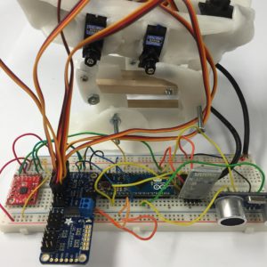
The image above shows the system integrated (without the battery) and connected to the 3rd generation of the BiRex prototype. To reduce the wiring of the main electronics system, we designed our own PCB on EagleCAD.
(Picture of PCB)
The image above shows the custom PCB for our BiRex. The details for how we designed in can be found on our PCB blog post. As previously mentioned, the production of a PCB reduces the complexity of wiring and creates a aesthetically pleasing look.
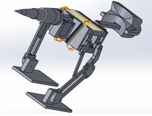
Considering this year’s Project Objective is a feasibility demonstration, the overall aesthetic design is not a high priority. In the image above, the yellow board represents the PCB, the wires represent the servo connectors, and the black cylinders represent wire looms. What is not seen is the battery (will be placed underneath the body), and the ultrasonic sensor (placed in front of the battery).
Conclusion:
As this project continues to progress into different Mission Profiles and Project Objectives, future generations can rely on the design innovations to understand how these changes affect the overall objectives. For example, the year’s model could potentially conceal the PCB by covering the back of BiRex with a 3D backbone print. The analog sensors (gyroscope and ultrasonic sensor) are limited to only be placed on the body (the neck, tail, and legs are mobile).


