Fall 2015 MicroBiPed PCB
PCB DESIGN
By Michael Balagtas (Manufacturing Engineer)
Approved by Paul Oo (Project Manager)
Approved by Railly Mateo (Systems Engineer)
Introduction:
The Final PCB layout is the responsibility of the Manufacturing engineer. To maximize the grade acquired for the assignment, a combination of through hole and SMD packages were utilized in the design.
Obstacles:
The problem presents itself when there are too many components on a board. Some components will have plenty of connections, sometimes to the point where there is no choice but to block other channels. Naturally, the solution to this would be to rotate the device. However, doing so can block even more channels. Another option is to create a double sided junctions. However, the double sided wires starts blocking other bottom sided channels utilized by other components. The only other option would be to go around it. Unfortunately, the free version of EAGLE has a limit of 2 in. x 2 ½ in; therefore, we do not have the liberty of space to maneuver around the conflicted part.

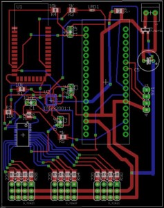
Final PCB Design. Note the part with the array of blue wires connected at the bottom left. That part is the servo driver, currently in the bottom of the board. Without it on the bottom, the order of the servo pins on the bottom would be convoluted.
The image above shows our finalized design for BiRex’s PCB. The red lines represent the copper tracing on top of the board, while the blue lines are underneath. An unpopular but effective method would be to have double sided SMD’s. By having an SMD on the bottom side, it is essentially mirrored by the axis that it is flipped on. This allows for some flexibility for routing.
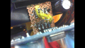
There were some unforseen problems, however. When the board was mounted on the robot, all of the parts were nominal except for the ultrasonic pins, which are the 4 pins on the right of the picture. The pins were oriented in such a way that the ultrasonic was facing backwards; we needed to mirror the pins somehow. We used a daughter board to jury rig the pins into flipping to correct the mistake, which is the brownish board in the following picture.

Conclusion:
In summary, if the design needs a mirror, a double sided PCB can be utilized. However, it is important to note that it can limit the mounting capabilities. Furthermore, when using Eagle, having a reliable mouse aids in alleviating the amount of controls needed to design.
