Fall 2015 MicroBiPed Stress Analysis
STRESS ANALYSIS USING SOLIDWORKS
By Michael Balagtas (Manufacturing Engineer)
Approved by Paul Oo (Project Manager)
Approved by Railly Mateo (Systems Engineer)
Introduction:
(This blog is written to accommodate stress test studies on strain heavy designs).
Previous Biped Robots had multiple joints connected by the servos. As such, it was easy to assume that, so long as the servo enclosure was thick and strong enough, the Biped could withstand the forces acted upon it during operation. However, for the 2015 BiRex design, the legs and joints are all connected via screws and nuts for articulation. Also, in order to reduce weight and size, some parts were thinned and holed, reducing their durability. This presents the team with a problem with the strain put on the joints and the parts as the BiRex moved.
Solidworks:
The parts had to be designed just enough to be easily manufactured and durable for walking. To accomplish this, the SimulationXpress feature on Solidworks was used to analyze the part for breaking points. The Simulation allows a user to determine which faces of the part will have a force applied into it (in the team’s case, the ankles) and which parts are stationary. It then allows the user to pick the specific type of material that the part is made out of, to determine the constants. By pressing run, the simulation starts calculating.
Results:

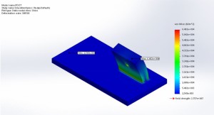
The von Mises test results. Solidworks allows you to determine which faces are stationary and which ones have forces acted on them. The ankle, which is the thick block, has all of the forces, and the red coloration indicates where the most vulnerable area is.
As a gauge, we considered the maximum force given by the robot as F = ma, which is the mass times the gravitational constant. In our case, 1.438 x 9.8 = 14.09N. The report indicated that the maximum force is above 65000N, which is way above our total forces.
The simulation then compiles a report in Microsoft Word that shows the simulation parameters and results. The most important is the von Mises Stress, which determines the force at which a material deforms. By being below this, the part is guaranteed to retain state after operation.
