Fall 2016 Biped – Color Sensor Experiment
Color Test Blog Post
By: Alan Valles (Electronics and Control)
Approved by: Ijya Karki (Project Manager)
Table of Contents
Introduction:
The purpose of this experiment is to find the optimal distance between the phototransistor, TCS 34725 photo transistor, and the surface of the object to be read. This distance will allow us to create a cavity on the inside of the foot with the right depth to properly house our instrumentation.
Analysis/Data:
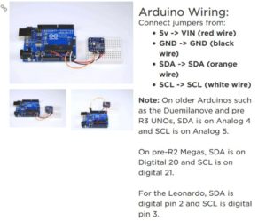
The Breadboard was set up as follows, and the guide that was followed was to set up per the adafruit directions found here:
https://learn.adafruit.com/adafruit-color-sensors/assembly-and-wiring
The Arduino Uno with an atmega328p was used as the microcontroller in this experiment. The sketch below prints the raw value of the color readings to the serial monitor.
First, a control reading was taken which grabbed the ambient color environment this value was found to be
Here is also some of the raw data from the output the important data that was used in the readings was the RGB values in the columns.
After tabulating all of the raw data from the serial monitor and was put in the table below.
As shown in the table below, the delta between the green value for the control was greatest at ⅛ of an inch. However, Based on observation As the color cards were closer to the phototransistor, at a certain point the sensor did not greatly distinguish between Green and Blue Construction paper. However, this could be due to the fact that the colors used were not BOLD. Therefore, the correct materials should be used as the color sensors, such as dark construction paper. The ambient light environment the experiment was performed in may have also led to alter the results. Since an on board LED will provide the lighting source, no other ambient light is needed. Therefore, under optimal conditions the cavity in the foot will be closed and will not allow light in. However, even with external environmental light, the phototransistor will function to some degree.
| Card | Control | 2inches | 1inch | ¾ inch | ½ inch | ¼ inch | 1/8 inch |
| Red | 123 | 167 | 304 | 442 | 697 | 1712 | 7168 |
| Green | 85 | 145 | 342 | 542 | 944 | 2535 | 12658 |
| Blue | 77 | 114 | 248 | 380 | 644 | 1707 | 8312 |
As a cautionary measure, and for added flexibility the recommended distance between the phototransistor and the floor is ¼ inch. This gives us enough room adjust the distance inside the assembled foot as needed. It will also operate at this exact distance. Even though ⅛ of an inch gives us a higher delta between the control reading, the added flexibility and additional room by creating the cavity ¼ of an inch will allow us to have more options when assembling the final robot. Also, at ⅛ inch there seemed to be similar readings between green and blue construction paper. However, this could be because the color of the object used. This color differentiation problem could be mitigated when choosing final materials for the power up pad.
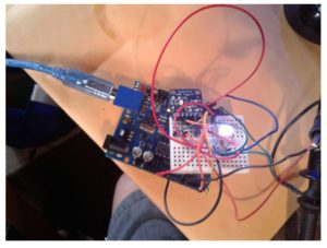
Figure 1: Realized Breadboard with RGB Matching LED
The LED is controlled using 3 digital pins from an Arduino Uno for this experiment. The functionality of controlling an indicator LED was also performed. During game play, the color will last for the duration of the power up length. This will be chosen at the discretion of the Game Committee and the Customer.
The code used was modified example code in the Adafruit_TCS34725 library.
#include <Wire.h>
#include “Adafruit_TCS34725.h”
// Pick analog outputs, for the UNO these three work well
// use ~560 ohm resistor between Red & Blue, ~1K for green (its brighter)
#define redpin 6
#define greenpin 3
#define bluepin 5
// for a common anode LED, connect the common pin to +5V
// for common cathode, connect the common to ground
// set to false if using a common cathode LED
#define commonAnode true
// our RGB -> eye-recognized gamma color
byte gammatable[256];
Adafruit_TCS34725 tcs = Adafruit_TCS34725(TCS34725_INTEGRATIONTIME_50MS, TCS34725_GAIN_4X);
void setup() {
Serial.begin(9600);
Serial.println(“Color View Test!”);
if (tcs.begin()) {
Serial.println(“Found sensor”);
} else {
Serial.println(“No TCS34725 found … check your connections”);
while (1); // halt!
}
// use these three pins to drive an LED
pinMode(redpin, OUTPUT);
pinMode(greenpin, OUTPUT);
pinMode(bluepin, OUTPUT);
// thanks PhilB for this gamma table!
// it helps convert RGB colors to what humans see
for (int i=0; i<256; i++) {
float x = i;
x /= 255;
x = pow(x, 2.5);
x *= 255;
if (commonAnode) {
gammatable[i] = 255 – x;
} else {
gammatable[i] = x;
}
//Serial.println(gammatable[i]);
}
}
void loop() {
uint16_t clear, red, green, blue;
tcs.setInterrupt(false); // turn on LED
delay(60); // takes 50ms to read
tcs.getRawData(&red, &green, &blue, &clear);
tcs.setInterrupt(true); // turn off LED
Serial.print(“C:\t”); Serial.print(clear);
Serial.print(“\tR:\t”); Serial.print(red);
Serial.print(“\tG:\t”); Serial.print(green);
Serial.print(“\tB:\t”); Serial.print(blue);
// Figure out some basic hex code for visualization
uint32_t sum = clear;
float r, g, b;
r = red; r /= sum;
g = green; g /= sum;
b = blue; b /= sum;
r *= 256; g *= 256; b *= 256;
Serial.print(“\t”);
Serial.print((int)r, HEX); Serial.print((int)g, HEX); Serial.print((int)b, HEX);
Serial.println();
delay(1500);// Added Delay in order to slow down serial monitor for reading.
//Serial.print((int)r ); Serial.print(” “); Serial.print((int)g);Serial.print(” “); Serial.println((int)b );
analogWrite(redpin, gammatable[(int)r]);
analogWrite(greenpin, gammatable[(int)g]);
analogWrite(bluepin, gammatable[(int)b]);
}
Conclusion:
The distance range most optimal for the placement of the color sensor is between ¼ inch and ⅛ of an inch. However, in order to increase assembly flexibility and aid in final assembly the cavity containing the foot should have at least ¼ inch of separation between the sensor and the ground.
References:
[1] https://learn.adafruit.com/adafruit-color-sensors/assembly-and-wiring[2] https://learn.adafruit.com/adafruit-color-sensors/programming


