Fall 2016 Prosthetic Hand – Critical Design Review
Project Manager – Kimberly Younger
Mission, Systems, and Test Engineer – Mia Lai
Electronics and Control Engineer – Younis Al-Kharusi
Design and Manufacturing Engineer – Wilson Mach
Table of Contents
Project Overview
Project Objective/Mission Profile
By Project Manager – Kimberly Younger
Mission Profile:
- As defined by the customer, the project mission of the prosthetic system shall allow a soldier requiring a prosthetic arm to eat a McDonald’s Quarter Pounder with Cheese meal. The prosthetic system will be designed to support the large community of wounded soldiers needing a prosthetic arm. While a fixture may be used to hold the meal, the other arm may not be used to feed the hungry soldier. In order to accomplish this goal, the prosthetic system will be manufactured as two separate entities, including a prosthetic arm and a prosthetic hand. The two entities will be able to attach and function as a single unit.
Project Objective:
- In order to achieve the mission profile, generalized program objectives needed to be qualified. The program objective is to use a part of the body that is not the hand to effectively control a prosthetic hand. The control would include wrist rotation ability and finger grasping ability. In conjunction with a Prosthetic Arm, the system would be able to feed someone a fast food meal without an allotted amount of time, being 20 minutes.
General Design
By Project Manager – Kimberly Younger
- Humanoid
- Five Fingers
- Palm Facing Flexion
- Gloved to Match Aesthetic of Arm
- Motors
- 5 DC Motors (Flexion)
- 1 Servo (Thumb Rotation)
- 1 Stepper Motor (Wrist Rotation)
- To be Added
- Wrist
- 4 FSRs on fingers
- Foot Control Panel
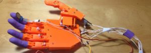
Figure 1: Printed and Assembled Hand (Back)
Figure 2: Printed and Assembled Hand (Front)
Project Features
By Project Manager – Kimberly Younger
Codependent Features
- PCB Housing in the Forearm
- Provided by Prosthetic Arm Group
- Kill Switch
- Emergency Power Off System provided by Prosthetic Arm Group
- Shared Power
- Integration Date: 11/19/2016
- Independent Control Systems
Figure 3: Solidworks View of Arm Prototype
Independent Features
- Wrist Turning
- Many independent Prosthetic Hands currently on the market do not offer any mechanism for pronation or supination of the wrist
- 7 Motors
- 5 DC motors for flexion, 1 Servo for thumb rotation, 1 Stepper for wrist supination
- Button Control from Foot
- A touch panel/button panel controlled by the foot/feet will control the motors
- Bluetooth
- Communication from foot to hand will happen wirelessly using an Xbee module
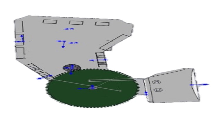
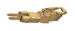
Figure 4: Solidworks View of Hand Prototype
Experiment Checklist
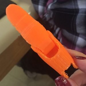
Figure 5: Sample 3D Prints (Completed)
Figure 6: Flexion Motion Model (Completed)
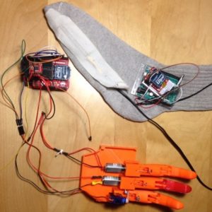
Figure 7: Bluetooth Model (Completed)
Figure 8: Motor Selection Experiment (Completed)
Figure 9: FSR Model (Completed)
Experiments to be Completed:
By Project Manager – Kimberly Younger
- Grasping Motion Experiment
- Wrist Model
- Joint Prosthetic System Experiments
System Block Diagram
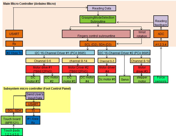
Figure 10: System Design Block Diagram
By Missions, System, and Test Engineer – Mia Lai
Subsystem Design
Interface Matrices
Figure 11: Main System Interface Matrix
By Missions, System, and Test Engineer – Mia Lai
Figure 12: Sub-System Interface Matrix
By Missions, System, and Test Engineer – Mia Lai
Figure 13: I2C 16-Channel PWM Driver Interface Matrices
By Missions, System, and Test Engineer – Mia Lai
Interface Control Matrix
Figure 14: Interface Control Matrix
By Missions, System, and Test Engineer – Mia Lai
More details about the Interface Control Matrix can be found in the Interface Control Document Blog Post.
Mission Command and Control
Figure 15: Mission Command and Control Diagram
By Missions, System, and Test Engineer – Mia Lai
System Flow Chart
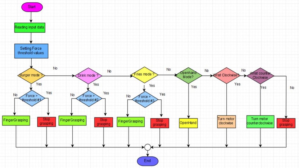
Figure 16: System Flow Chart
By Missions, System, and Test Engineer – Mia Lai
Electronic Design
Figure 17: Electronic Design Flow Chart
By Electronics and Control Engineer – Younis Al-Kharusi
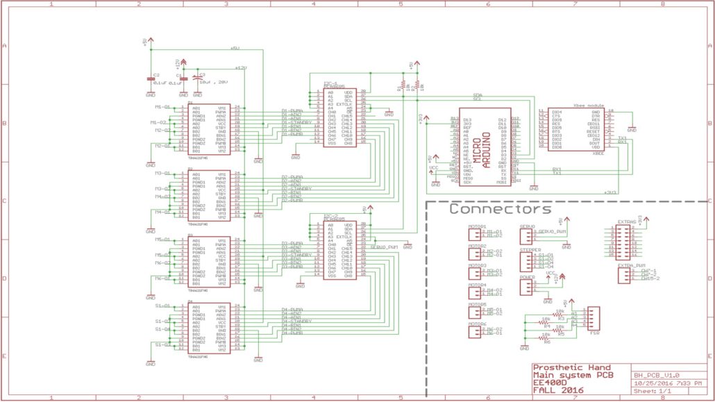
- PCA9685 16-channel, 12-bit PWM Driver
- I2C bus controlled (22 I/O pins required to control 7 actuators)
- Adjustable frequency from 24Hz to 1526 Hz (50Hz required to drive the servo)
- 16 programmable 12-bit PWM channels (14 channels used for 2 motor drivers)
- TB6612FNG Dual Motor Driver
- 1.2 A average and 3.2 A peak current per channel (1.5 A max required for stepper motor)
- 15V Max (12V required)
- Force Sensitive Resistor (FSR)
- Sense up to 20 N force (13.4 N required)
- Adafruit 12-Key Capacitive Touch Sensor Breakout
- Handles up to 12 touch sensors (6 required for Touch Panel)
Firmware
By Electronics and Control Engineer – Younis Al-Kharusi
Libraries
<Wire.h>
- //I2C communication
<Adafruit_PWMServoDriver.h>
- //used to control PCA9685
- //used to control touch panel
Modules
motordriver_setup();
- //sets up pins on the motor drivers
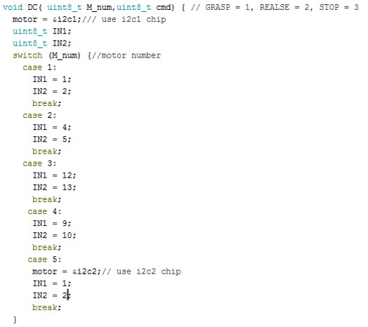
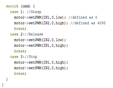
DC(Motor Number, Command) ;
- // Control DC motors (GRASP =1,RELEASE =2,STOP=3)
servo(degrees);
- //control servo using PCA9685
Stepper(Direction);
- //Control stepper motor (CW=1,CCW=2)
read_force();
- //read force sensors data
I2C Communication
Controlling DC Motors
Main Loop
A Look Inside the Main Loop: Drink Mode
PCB
Fritzing Diagram
Figure 18: Fritzing Diagram
By Electronics and Control Engineer – Younis Al-Kharusi
Breadboard Implementation
Figure 19: Breadboard Implementation
By Electronics and Control Engineer – Younis Al-Kharusi
Schematic
Figure 20: PCB Schematic
By Electronics and Control Engineer – Younis Al-Kharusi
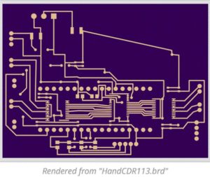
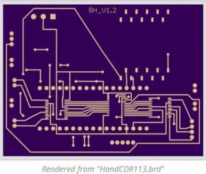
Layout
Figure 21: PCB Layout
By Design and Manufacturing Engineer – Wilson Mach
Note that the PCB will be nested inside of the forearm and is restrained by the size of the forearm. This PCB was constricted to a 2 layer SMD within 3×2.25 inches.
Figure 22: PCB Bottom Layer
Figure 23: PCB Top Layer
Hardware Design
By Design and Manufacturing Engineer – Wilson Mach
Modeling
Figure 23: Prosthetic Hand Completed Model
These two models show the fully assembled hand with the wrist/palm/arm connection. To the top left is the hand in a pinching position, which will be used for the pinching of French fries. To the top is the hand in a grasping position, which will be used for the grasping of the drink cup. In addition, the transparent view, on the top right, shows the inner workings and screws that are not visible to the outside. To the middle right is a 3D model made with Photo View 360, showing the hand in a pointing position.
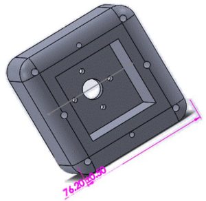
The wrist connection is a unique “from scratch” design. The connector features a stepper motor and slip ring. Multiple models were constructed to serve as an appropriate interface between the forearm and hand. These models included changes in hole size, fastener diameter, and palm size. This model, shown on the bottom right allows for rotation, from the stepper motor, at the center of mass.
Figure 24: Prosthetic Hand Completed Model- Transparent
Figure 25: Prosthetic Hand Pointing
Figure 26: Wrist Model
Verification Highlights
By Mission, Systems, and Test Engineer – Mia Lai
- R2.1 – Grip Force
- Using a test verification method, grip force will be verified using a dynamometer. The success criteria should be 13.4 N or greater.
- R2.1.1 – DC Motor Torque
- Using a test verification method, the DC motor will be tested to ensure a minimum torque of 0.14 Nm.
- R2.3 – Sensor Feedback System
- Using both a test and demonstration verification method, the hand will demonstrate the ability to turn off actuators when force applied is above the threshold for the particular item. (Burger Mode – 2.3 N; Drink Mode – 0.68 N; Fries Mode – 0.04 N)
- R11.1 – Noise Level
- Using a test verification method, the prosthetic system shall demonstrate operation below a noise level of 60 dB.
Validation Highlights
By Mission, Systems, and Test Engineer – Mia Lai
- Customer Evaluates Grasping Function
- By demonstration, the hand is able to grasp three different meal items: Quarter Pounder with Cheese, McDonalds medium soft drink, and French fries.
- Customer Evaluates Grip Strength
- By demonstration the hand will be able to grasp and hold onto the heaviest food item, being the medium soft drink.
- Customer Evaluates Feedback
- By demonstration, the hand will stop increasing pressure applied to the food items.
- Customer Evaluates Wrist Rotation
- By demonstration, the hand will rotate from the base of the palm at the “wrist” joint.
- Customer Evaluates Control
- By demonstration, the customer will use his/her foot to control the prosthetic hand.
Project Status
Project Schedule
Figure 27: Top Level Schedule
By Project Manager – Kimberly Younger
The schedule is broken up into project phases, with each phase having underlying sub level tasks. In the interest of relevance, the sub level tasks are shown only for the Assembly/Test Phase.
Figure 28: Critical Path
By Project Manager – Kimberly Younger
The critical path follows the two design phases, test phase, and project launch. The most crucial and potentially volatile part of this path is the integrated testing that must be done within the Assembly/Test phase.
Burn Down
Figure 29: Burn Down Chart
By Project Manager – Kimberly Younger
This burn down chart demonstrates the timeline of the project in terms of percentages and tasks left. The project percent completion indicates past as well as projected completion rates according to the project schedule.
Mass Report
Figure 30: Mass Allocation Report
By Mission, Systems, and Test Engineer – Mia Lai
Power Report
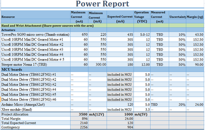
Figure 31: Power Allocation Report
By Mission, Systems, and Test Engineer – Mia Lai
Cost Report
Figure 32: Cost Allocation Report
By Project Manager – Kimberly Younger
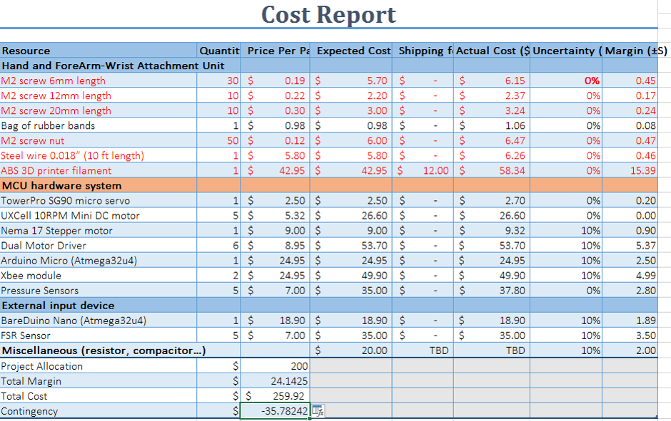
All items shown in red are provided by the customer and are not included in the total costs.
Previous:
- Project Allocation – $400
- Total Margin – $50.02
- Total Expected Cost: $387.33
- Contingency: $62.69
Current:
- Project Allocation – $200
- Total Margin – $24.15
- Total Expected Cost: $259.92
- Contingency: $-35.79


