Fall 2016 Prosthetic Hand – Preliminary Design Document
Project Manager – Kimberly Younger
Mission, Systems, and Test Engineer – Mia Lai
Electronics and Control Engineer – Sara Gonzalez
Design and Manufacturing Engineer – Wilson Mach
Table of Contents
Preliminary Research
Mission Profile
By Project Manager – Kimberly Younger
As defined by the customer, the project mission of the prosthetic system shall allow a soldier requiring a prosthetic arm to eat a McDonald’s Quarter Pounder with Cheese meal. The prosthetic system will be designed to support the large community of wounded soldiers needing a prosthetic arm. While a fixture may be used to hold the meal, the other arm may not be used to feed the hungry soldier. [1] In order to accomplish this goal, the prosthetic system will be manufactured as two separate entities, including a prosthetic arm and a prosthetic hand. The two entities will be able to attach and function as a single unit.
Straw Man Presentation
Straw Man Prezi
Compiled by Project Manager – Kimberly Younger
All preliminary research to understand the prosthetic hand market and to find a suitable straw man was summarized in a presentation that can be assessed clicking the title “Straw Man Prezi” above or the link below.
https://prezi.com/5mvblrhzsqcv/the-robot-company-bionic-hand/?utm_campaign=share&utm_medium=copy [2]
Creativity Exercises
Creativity Presentation
Compiled by Project Manager – Kimberly Younger
Creativity Exercises such as lateral thought, brain writing, attribute listing, and Duncker diagrams were used to find creative solutions and experiments to problems. The exercises and results can be accessed by clicking the title “Creativity Presentation” above or the link below. [3]
https://www.dropbox.com/s/1wr9et1x9z4vo3c/Bionic%20Hand%20-%20Creativity%20Exercise.pptx?dl=0
Research References
[1] EE 400D F’16 Project Objectives and Mission Profile by Gary Hill
http://web.csulb.edu/~hill/ee400d/F’16%20Project%20Objectives%20and%20Mission%20Profile.pdf
[2] The Robot Company: Bionic Hand Preliminary Research Presentation by Kimberly Younger
http://prezi.com/5mvblrhzsqcv/?utm_campaign=share&utm_medium=copy&rc=ex0share
[3] Bionic Hand Creativity Exercise by Kimberly Younger
Requirements
Project requirements break down the large task of creating a device into its fundamental components. These requirements define the basic necessities of the project and guide their implementation. Level 1 project requirements are crucial project requirements that help define the project. Level 2 system requirements describe the systems that will be enacted to ensure project requirements are met. Finally, level 2 subsystem requirements specify even further how system goals will be met.
The level 1 project requirements are indicated by an RX, where X is the number of the requirement. The level 2 system requirements are indicated by an RX.X. The first number indicates the level 1 requirement from which it is derived and the second number labels the specific level 2 requirement. The same numbering scheme is used for subsystem requirements by RX.X.X.
Level 1 Project Requirements
By Project Manager – Kimberly Younger
By Mission, Systems, and Test Engineer – Mia Lai
R1 – The Prosthetic Hand will be a functional component of the Prosthetic System by having capabilities to attach and work with the Prosthetic Arm.
R2 – The Prosthetic Hand shall feed a person a McDonald’s Quarter Pounder with Cheese meal (as defined by the McDonald’s website [2]) within twenty minutes of first picking up the meal.
R3 – The Prosthetic Hand shall be capable of picking up a medium drink/malt, Quarter Pounder with Cheese, and bundles of French fries (1-10 fries per bundle) without breaking the cup/food item.
R4 – The Prosthetic Hand movements shall not be controlled by the other hand.
R5 – The total cost of the project shall not exceed 400 USD.
R6 – The project shall be completed on or before the end of the CSULB Fall 2016 Semester, which is 12/22/2016, as defined by the CSULB Academic Calendar [7].
Level 2 System and Subsystem Requirements
By Mission, Systems, and Test Engineer – Mia Lai
By Electronics and Control Engineer – Sara Gonzalez
R1 – The Prosthetic Hand will be a functional component of the Prosthetic System by having capabilities to attach and work with the Prosthetic Arm.
- R1.1 – The Prosthetic Hand shall connect to the Prosthetic Arm at the base of the wrist.
- R1.1.1- The maximum weight of the prosthetic hand should not exceed 5 lbs. [1]
- R1.2 – The Prosthetic Hand shall include rotation in the wrist.
- R1.2.1- The wrist of the Prosthetic Hand shall have a diameter between 3-5 inches in order to meet size requirements dictated by the Prosthetic Arm group.
R2 – The Prosthetic Hand shall feed a person a McDonald’s Quarter Pounder with Cheese meal (as defined by the McDonald’s website [2]) within twenty minutes of first picking up the meal.
- R2.1 – To accommodate the meal time, the battery that will be used shall last at least 20 minutes.
R3 – The Prosthetic Hand shall be capable of picking up a medium drink/malt, Quarter Pounder with Cheese, and bundles of French fries (1-10 fries per bundle) without breaking the cup/food item.
- R3.1 – The grasping speed of the hall shall be between 115 degrees per second and 250 degrees per second. Grasping speed is defined by the speed of the hand from an opened position to a closed position. This speed was suggested as most practical by Joseph Belter of the GRAB lab at Yale University [3].
- R3.1.1 – The grasping speed will be controlled via a motor driver connected to an Arduino Uno and Arduino IDE software, as demonstrated by the TACT Hand. [4]
- R3.2 – There shall be preprogrammed grasping patterns for the hand, including cylindrical grasp, rectangular grasp, and a pinch grasp.
- R3.2.1 – The cylindrical grasp shall pick up 500-700 grams of liquid, as is standard soft drink mass for a 21 ounce cup. [2]
- R3.2.2 – The rectangular grasp shall pick up 160-180 grams of burger, as is standard Quarter Pounder with Cheese size. [2]
- R3.2.3 – The pinch grasp shall pick up 2-30 grams of fries at a time, as it is standard for one French fry to weigh 2 grams. [2]
- R3.3- The average force of the grip on an object shall not exceed 5 Newtons [4].
- R3.3.1 – The pressure applied by the prosthetic fingers on each food object shall have a force accuracy range between ±5% to ±25%, in order to accommodate the margin of error of force sensitive resistors. [5]
R4 – The Prosthetic Hand movements shall not be controlled by the other hand.
- R4.1 – The prosthetic hand shall have an input device that allows the users to use their feet to control the unit.
- R.4.1.1 – The external controller shall connect and control the prosthetic hand wirelessly with a minimum range of 0 feet and a maximum range of 200 feet, in order to remain in the communication range of the Bluetooth mechanism of the hand. [6]
R5 – The total cost of the project shall not exceed 400 USD.
R6 – The project shall be completed on or before the end of the CSULB Fall 2016 Semester, which is 12/22/2016, as defined by the CSULB Academic Calendar. [7]
Requirements References
[1] Mass Requirements
https://www.arduino.cc/en/Main/ArduinoBoardUno
https://www.sparkfun.com/products/13197
https://www.pololu.com/product/1182
http://rogerparks.com/instructional/escap-16-gear-motor-encoder/
http://www.servodatabase.com/servo/towerpro/sg90
https://www.adafruit.com/products/166
[2] McDonald’s Quarter Pounder with Cheese Meal
https://www.mcdonalds.com/us/en-us/about-our-food/nutrition-calculator.html
[3] Joseph Belter Grasping Speed
http://www.rehab.research.va.gov/jour/2013/505/page599.html
[4] Tact: Low Cost, advanced Prosthetic Hand
http://www.instructables.com/id/Tact-Low-cost-Advanced-Prosthetic-Hand/?ALLSTEPS
[5] FSR Integration Notes
https://cdn-learn.adafruit.com/assets/assets/000/010/126/original/fsrguide.pdf
[6] XBee Trace Antenna
https://www.sparkfun.com/products/11215
[7] CSULB Academic Calendar
Breakdowns
Work Breakdown Structure
Figure 1: Work Breakdown Structure (WBS)
By Project Manager – Kimberly Younger
In order to complete the prosthetic hand prototype within the 15 week semester deadline, a work breakdown structure was created. This structure outlines the project specific requirements for each member of the team.
Product Breakdown Structure
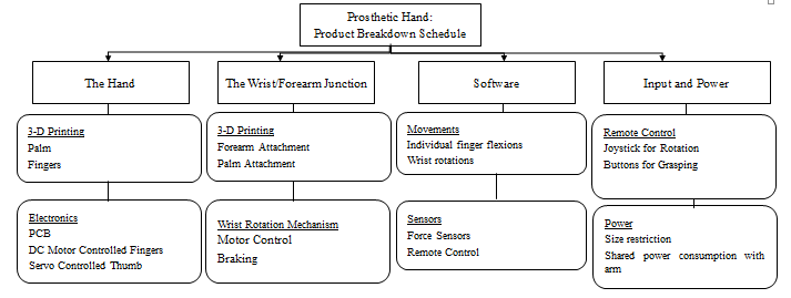
Figure 2: Product Breakdown Structure (PBS)
By Mission, Systems, and Test Engineer – Mia Lai
This Product Breakdown Structure (PBS) outlines fundamental parts of the Prosthetic Hand project. The hardware is split into two categories include the hand and the wrist/forearm junction. These categories have subcategories for 3-D printing as well as mechanical or electrical specifications. Next, the software category addresses the sensors and actuator requirements as they will be used for and controlled by the software. Finally, input and power designations have their own category.
Budget Breakdown
Figure 3: Budget Breakdown
By Electronics and Control Engineer – Sara Gonzalez
As demonstrated in the budget breakdown, the projected cost of the device is $343.67. The prior predicted cost and required cost of their device is $400. The slight excess will be maintained for emergency changes that may be required from the parts or other unpredictable set backs.
Electronic System Design
System Block Diagram
Figure 4: System Block Diagram
By Missions, System, and Test Engineer – Mia Lai
This block diagram shows the basic flow of the signals. Force sensitive sensors will send signals to analog pins on the Arduino Uno while the input device will work with a custom shield to provide another form of input. On the output, digital I/O pins will be connect to a custom PCB that will control the actuators.
PCB Design
By Electronics and Control Engineer – Sara Gonzalez
For the prosthetic hand, the PCB design will be for the motor driver being used to communicate between the Arduino Uno and 5 DC Coreless motors and SG90 Servo used for the flex motion of the fingers and rotation of the thumb respectively is still a work in progress.
Since the Prosthetic Hand is working jointly with the Prosthetic Arm to create the Prosthetic System, much collaboration between each division is essential. After many collaborative meetings with the electronics and control engineer from the Prosthetic Arm, a design for the A4988 stepper motor driver was shared and recommended for the stepper motor being used to rotate the wrist [1]. Photos of the design can be seen in Figures 5 and 6 below.
Figure 5: Eagle CAD Schematic of A4988 Motor Driver [1]
Figure 6: Second Eagle CAD Schematic of A4988 Motor Driver [1]
Sensors, Actuators, and Power
By Electronics and Control Engineer – Sara Gonzalez
Sensors-
The sensors being used on the prosthetic hand will be a force sensitive resistor (FSR) by Adafruit [2]. These pressure sensors will be placed on 3-5 of the fingertips of the prosthetic hand. This will allow the gripping motion of the fingers to stop once an object is touched or come in contact with. The technical details and a photo of the sensor is shown below in Figure 7 [2].
Actuators-
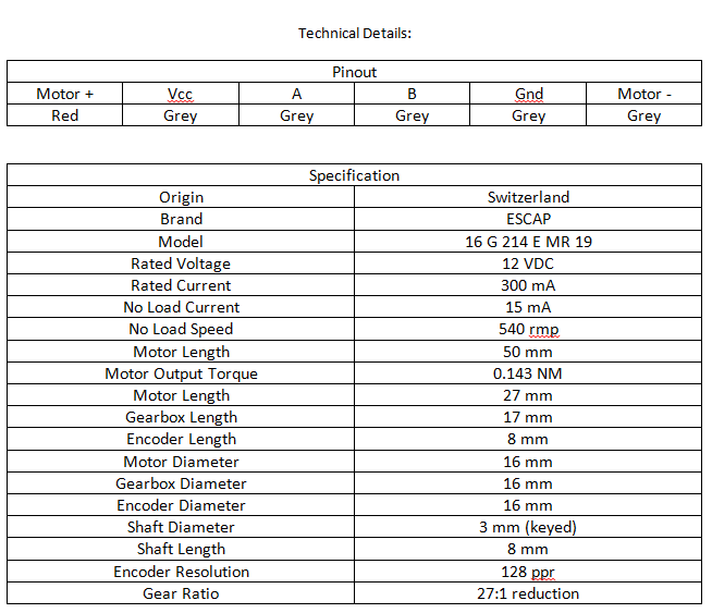
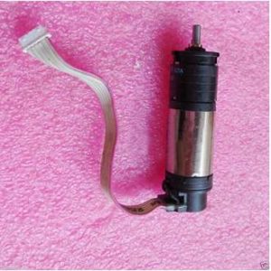
ESCAP 16 DC Coreless Gear Motors: These motors will be used to generate the bending motion of each finger on the prosthetic hand. The pinout chart, specifications and photo of this motor in Figure 8 can be found below [3].
TowerPro SG90 Servo Motor: This motor will be used for generating the rotation of the thumb inwards towards the palm of the prosthetic hand. The specifications and a photo of this servo in Figure 9 can be found below [5].
Stepper Motor: This motor will be used to generate the clockwise and counter-clockwise rotation of the wrist for the prosthetic hand. This motor will be place in the portion of the forearm of the prosthetic arm closest to the hand. The specifications for this motor have not yet been determined but will be decided together with the Prosthetic Arm group.
Figure 8: Image of ESCAP 16 Gear Motor with Encoder [4]
Figure 9: Image of SG90 Servo Motor [6]
Power-
A power source for this design has not yet been determined, but will be discussed with the Electronics and Controls engineer for the Prosthetic Arm project. A shared power source for both the hand and arm when combined is desired.
MCU Subsystem and Control Firmware
By Electronics and Control Engineer – Sara Gonzalez
Arduino Uno-
The Arduino Uno will be used to control 3 pieces of hardware: the XBee Shield, XBee Module and DFRobot Joystick/Input Shield for Arduino. It will be programmed using Arduino IDE. The specifications and image of the device in Figure 10 can be found below [7].
Figure 10: Image of Arduino Uno [7]
XBee Shield –
Will be used to connect to the Arduino and hold the XBee Module. The specifications and schematic of the shield in Figure 11 can be found below [8].
Figure 11: Image of XBee Shield Schematic [8]
XBee Module –
Will be used to allow the external controller (DFRobot Joystick/Input Shield for Arduino) to control the prosthetic hand wirelessly. The specifications and image of module in Figure 12 can be found below [9].
Figure 12: Image of XBee Module [9]
DFRobot Joystick/Input Shield for Arduino-
Will act as the external, wireless controller for the prosthetic hand. Will be attached to an Arduino and hold a transmitting XBee module. The specifications for this shield and image in Figure 13 can be found below [10].
Figure 13: Technical Details of DFRobot Joystick/Input Shield for Arduino [10]
Electronic System Design References
[1] A4988 Stepper Motor Driver Carrier
https://www.pololu.com/product/1182
[2] Round Force-Sensitive Resistor by Adafruit
https://www.adafruit.com/products/166
[3] ESCAP 16 Gear Motor with Encoder
http://rogerparks.com/instructional/escap-16-gear-motor-encoder/
[4] ESCAP 16 Coreless Motor
http://www.ebay.com/itm/ESCAP-16-Coreless-DC-12V-540RPM-Gear-Motor-With-Encoder-16MM-/181537865905
[5] TowerPro SG90 Servo Specifications and Reviews
http://www.servodatabase.com/servo/towerpro/sg90
[6] TowerPro SG90 Servo
http://forum.arduino.cc/index.php?topic=119983.0
[7] Arduino – ArduinoBoardUno
https://www.arduino.cc/en/Main/ArduinoBoardUno
[8] SparkFun XBee Wireless Kit – KIT-13197 – SparkFun Electronics
https://www.sparkfun.com/products/13197
[9] XBee 1mW Trace Antenna – Series 1 (802.15.4) – WRL-11215 – SparkFun Electronics
https://www.sparkfun.com/products/11215
[10] DFRobot Joystick / Input Shield for Arduino
Manufacturing Design
By Design and Manufacturing Engineer – Wilson Mach
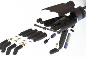
For this project we will be using a 3D printer to build the parts in ABS plastics. In order to have the parts printed in a 3D printer, we need to model the parts with software called SolidWorks. With this CAD software, we are able to design all the segments of the bionic hand model to have our first prototype for testing. We decided to use four fingers and a thumb as a human would have, however we be using two segments for each fingers instead of three. Each segment of the finger will be joined together will a spool and lock in with small M2 screws for freedom to curve them. The spool is then tied up with a steel wire at one end and connected to the wire of a DC motor on the other end to have a pulley motion for the fingers to curl. All four fingers and the thumb will be controlled by the motor, which will be commanded via microcontroller, to operate the hand to perform special grip movements.
The ABS plastics are very light and sturdy at the same time, so we believe using 3D printing is the best choice to meet level requirement without too much weight on the hand. If we need a stronger motor to perform a tighter grip we can change the infill of the 3D printer to put more layers into each part of the fingers to have it 100% solid for a more sturdy hand. The weight may increase if we decided to have the fulfilling, however we will try to limit our weights to 5 pounds.
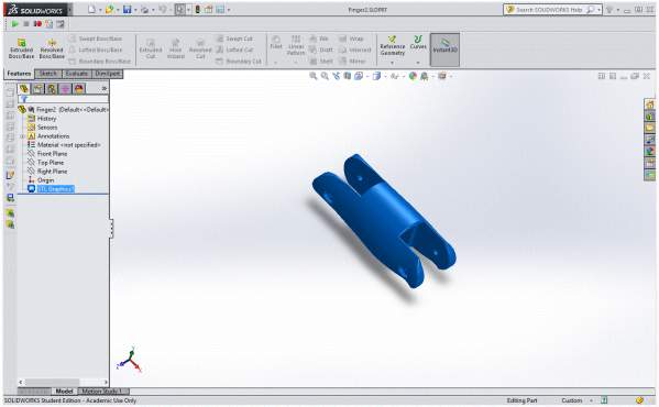
Figure 14: Finger SolidWorks
This figure shows a SolidWorks representation of a segment of the finger to be 3D printed.
Figure 15: Finger Rapid Prototype
This figure shows the finger prototype of the finger to be used. This, or fingers like it, will be used in the rapid prototyping phase of the project in order to use something that will be similar to the final product.
Figure 16: Finger Rapid Prototype – Set Up
This figure shows the built prototyped finger that was referenced in the figure above.
All files were retrieved from the TACT hand that is available online [1].
Manufacturing Design References
Design and Unique Tasks
By Missions, System, and Test Engineer – Mia Lai
By Project Manager – Kimberly Younger
- Determine size and dimensions of wrist/arm connector by working with Prosthetic Arm Group (Due 10/6/2016)
- Simulate Grasping Motion using a Rapid Prototype (Due 10/6/2016)
- Simulate Control Mechanism using a Rapid Prototype (Due 9/29/2016)
- Research about Bluetooth configurations, advantages, and disadvantages (9/29/2016)
- Determine power requirements for the prosthetic hand and prosthetic system (Due 10/6/2016)

