Fall 2016 Prosthetic Hand – Preliminary Project Plan
Project Manager – Kimberly Younger
Mission, Systems, and Test Engineer – Mia Lai
Table of Contents
Work Breakdown Structure
By Project Manager – Kimberly Younger
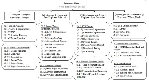
In order to complete the prosthetic hand prototype within the 15-week semester deadline, a work breakdown structure was created. This structure outlines the project specific requirements for each member of the team.
The work breakdown structure is organized into four branches that align with the four members of the project team. Each branch depicts the duties of the particular engineer in relation to the project development.
Using the model provided Preliminary Project Plan PDF [1], this WBS was created.
Figure 1: Work Breakdown Structure
WBS References
[1] Preliminary Project Plan Documentation Lecture
Project Schedule
Top Level Schedule & System/Subsystem Requirements
By Project Manager – Kimberly Younger
The Project Schedule depicts the details from the work breakdown structure in a chronological manner. The schedule shows how tasks will depend on one another and how time will need to be used in order to adequately finish the project in the allotted period of time.
In the following schedules, tasks are assigned to group members, including a start date and end date.
At a top level, this project schedule is organized in phases, depicting system/subsystem level tasks within each phase. Each specific task has an assigned group member. Any unassigned tasks are the responsibility of the group together.
Figure 2: Project Schedule
Burn Down and Percentage Completion
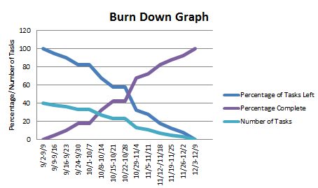
Figure 3: Burn Down Chart
By Project Manager – Kimberly Younger
A burn down chart compares remaining work (number of tasks as defined by the project schedule) with time, in order to depict anticipated project progress. As portions of the project are completed over time, the anticipated remaining workload decreases.
System Resource Allocations
By Mission, Systems, and Test Engineer – Mia Lai
Cost Allocation
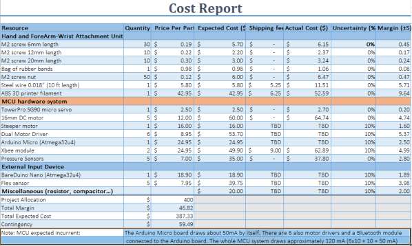
The original allotted budget for the Prosthetic Hand, as listed in the Preliminary Design Document, was $400. Of this $400, about $150 was excess. However, after doing more research, the cost of the product seems to be much closer to the $400 mark, though not exceeding it. In order to maintain the budget, precautions must be taken as to not spend money on unnecessary items.
The report shows expected cost and parts for building our prosthetic hand project. The actual cost includes sale tax and shipping fee. For parts that we have not purchased, the margin is 10% uncertainty (8% sale tax and 2% shipping fee) of the expected cost. The total expected cost of the project is $387.33, which is every closed to our project allocation. The contingency for unforeseeable cost is $59.49
Figure 3: Cost Allocation Report
Mass Allocation
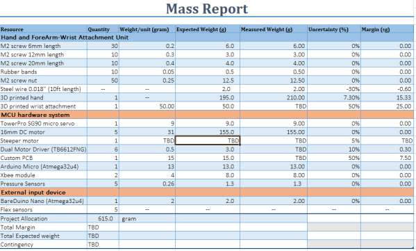
As defined by current requirements, the mass of the hand needs to be between 350-1350 grams. According to the Mass Report shown below, the hand should weigh in at about 615.0 grams. This is well within the required goal.
This report shows the parts that we will use to build prosthetic hand. The steeper motor will be determined after we conduct a rapid prototyping study. The expected weight of the hand (without mass of the stepper motor) is 479.3 g. The mass allocation of our project is 615 gram.
Figure 5: Mass Allocation Report
Power Allocation
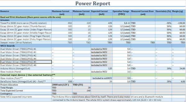
Power will be shared with the Prosthetic Arm group in order to have the Prosthetic System run under one power unit. In order to maintain this efficiency, it is imperative that power system requirements are clear, concise, and accurate. Both groups must work together to ensure that their power needs are met. The following report shows the anticipated power needs for the Prosthetic Hand.
This power report is designated only for the Prosthetic Hand. The power allocation will be more finely specified after conducting rapid prototyping with the actuators.
Figure 6: Power Allocation Report
Allocation Reports References
[1] TowerPro SG90 micro servo
http://www.towerpro.com.tw/product/sg90-7
[2] 16mm DC motor
[3] Technical specification for Dc motor
[4] Dual Motor Driver
https://www.sparkfun.com/products/9457
[5] Arduino Micro (Atmega32u4)
https://store-usa.arduino.cc/products/a000053
[6] Xbee module
https://www.sparkfun.com/products/11215
[7] Pressure Sensors
https://www.adafruit.com/product/166
[8] BareDuino Nano (Atmega32u4)
https://www.seeedstudio.com/BareDuino-Nano-p-1545.html
[9] Flex sensor
https://www.sparkfun.com/products/10264
[10] M2 screw 6mm length
https://www.amazon.com/Team-Losi-Flathead-Screws-6mm/dp/B004EWZ3NY
[11] M2 screw 12mm length
[12] M2 screw 20mm length
[13] Bag of rubber band
https://www.amazon.com/Universal-00132-32-Size-Rubber-Bands/dp/B0007893SU?th=1
[14] M2 screw nut
[15] Steel wire 0.018” (10 ft length)
http://www.mcmaster.com/#catalog/122/1452/=14dulko
[16] ABS 3D printer filament


