Fall 2016 Solar Panels: Creating a Port Expander Using IC MCP23017
By Jose Rodriguez (Electronics & Control)
Approved By Inna Echual (Project Manager)
Objective: Because of our current design, a port expander is needed because there are no more available pins on our Arduino to read data from the reed switches. The reed switches will be used to halt the panels from cocooning more than it needs to; if it goes past a certain angle, it could hit the adjacent panel and damage its cells.
How to Set Up the IC
The Microchip MCP23017 is a 16-bit serial expander with I2C serial interface. This 28-pin IC offers sixteen inputs or outputs. Figure 1 shows the pinout data sheet for the IC:

Figure 1: MCP23017 Pinout [1]
Firstly, the expander was checked to see if it worked using two LEDs, which will be set high and low using the IC. Note that there are two banks, A and B, and each bank has a total of 8 pins. Both banks will be used in this blog to understand either or both of their activations.
The code in Figure 2 is used to set up ports as outputs. The address for the device can be found on the data sheet [2], but to save time it is x20. To set pins as input, a one need to be set on the fourth column of the code depending on the required pin. Hex values are used, so for example, FF will set all pins as inputs. F0 sets the first 4 pins as inputs and the last 4 pins as outputs.

Figure 2: Code to Set Up Input and Output Ports
Once setup is complete, it becomes simple to set ports as high or low. The code in Figure 3 shows how to set up the pins using binary values. Four lines of code are needed to write on pins. The code takes a lot of space but there is a library that has been made for the MCP23017 by Adafruit that adds 1,000 bytes of memory.
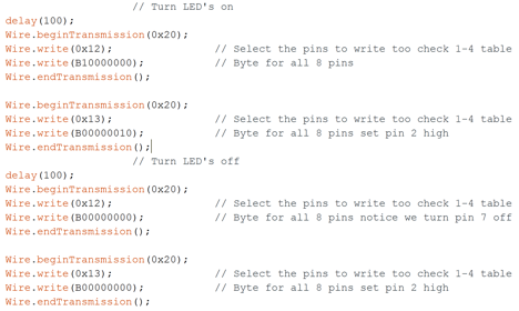
Figure 3: Code to Set up Pins
The Adafruit library needs to be downloaded and saved in the Arduino library because it can be used with the IC. The code for using the library is shown in Figure 4. First the Adafruit library has to be included by writing #include. The code from Adafruit is similar to that of the Arduino when it comes to setting up pins, but mcp. needs to be added before pinMode. The setup is straight forward however note that Bank b refers to pins 8 to 15.
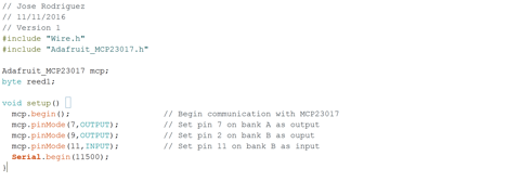
Figure 4: Code to Use Adafruit Library
Alternatively, the following code in Figure 5 turns two led on and off, but is more efficient as it requires less code. Either method can be used but the latter is cleaner than the other. If memory code is an issue, then the longer method (firts code) will be optimal to save memory.

Figure 5: Alternative Code to Light LEDs
Conclusion
Adding a port expander is not as hard as one will think as using the Adafruit library makes the process even easier. To read a pin the command that will be needed is mcp.digitalRead only. The second method makes the code cleaner, but the first method gives an individual an idea of what is going on behind the second method.
References
[1] Maximising your Arduino’s I/O ports with MCP23017: http://tronixstuff.com/2011/08/26/tutorial-maximising-your-arduinos-io-ports/ [2] MCP23017 Data Sheet: http://ww1.microchip.com/downloads/en/DeviceDoc/21952b.pdf