Fall 2016 Solar Panels: Project Summary
By Inna Echual (Project Manager)
Table of Contents
Project Overview
Executive Summary
Project Objective
The design of the Fall 2016 Pathfinder project was taken directly from NASA’s Mars Exploration Rovers, Opportunity and Spirit. The Pathfinder will be designed to be self-sufficient using solar panels, as well as implement the solar deployment mechanism employed by the two aforementioned rovers. The solar panels should able recharge the Pathfinder’s battery allowing it to traverse rough terrain. The solar panels must also articulate to track the sun, maximizing the amount of solar power received.
Mission Profile
The project will be demonstrated by parking the Pathfinder in the Central Quad on California State University, Long Beach located at 33°46’40.7″N 118°06’48.9″W. In addition to the location near the defined travel course, the parking spot was chosen as it had low traffic and free of shading. The parking spot is indicated in Figure 1.

Figure 1: Pathfinder Charging Spot

Figure 2: Pathfinder Charging Spot (Magnified)
Project Features
-
Customized Solar Panels
This will be done using 5 strings in parallel of 30 solar cells stringed together in series to fit the customized solar shape of the aforementioned rovers (see compare our layout in Figure 3 with Spirit’s layout in Figure 4).

Figure 3: Fall 2016 Solar Panels

Figure 4: Spirit Rover Panels
-
Panel Proportionality
The solar panels will be configured to be identical to the form factor of the solar panels on the Opportunity and Spirit rovers (see Figure 5).

Figure 5: Form Factor Consideration
Experiments Checklist
- Experiments on Solar Cell Cutting and Efficiency to determine stringing
- Back of the Envelope calculations to determine stringing and layout
- Experiment using MPU 6050 to determine rover balance
- Experiment using DC motor as a stepper motor with an encoder
- I2C – test communication between Arduino Uno and Arduino Mega
- Sun tracking with photo resistors
System Design
System Block Diagram

Figure 6: Updated System Block Diagram from CDR
Updated System Block Diagram from CDR brief.
Subsystem Design
Interface Definition
Interface Matrix

Figure 7: Interface Matrix
Interface Control Document
As defined in the mission profile, the Pathfinder will be allowed to travel a course on the upper campus of CSULB. This system is designed to replicate the Spirit & Opportunity Mars Rovers. The program objective is to be self-sufficient. In order for this system to be successful with it’s mission, the two systems; Chassis & Solar Panel, must work together with one another. The Solar Panel will be in charge of supplying power to the battery, and the Chassis will then be able to use this battery and travel the course.
The Interface Control Document will be used to provide an outline for the responsibilities aligned with each system. It also sets out the interfacing requirements to help move the design forward for each of our systems in the following disciplines: Mechanical Interfacing, Power Transactions, and Control Mechanism & Data Transfer. It also includes some constraints, assumptions, and possible risks involved in these factors.
Interface Control Document
Mission Command and Control
Software Block Diagram

Figure 7: Software Block Diagram
The software block diagram in Figure 7 explains an overall understanding of what the Solar Panel system’s software entails. It also includes a portion of the Chassis system and how we are interfacing with one another electronically, along with a legend on the bottom left to help detect what the different colors mean.
Electronics Design
DC Motor With Encoder Experiment
Creating a Port Expander Using IC MCP23017
Firmware
PCB Schematic

Figure 8: Fritzing Diagram for Motor Driver

Figure 9: Fritzing Diagram for I2C Communication

Figure 10: Breadboard for Motor Driver

Figure 11: Schematic
PCB Layout
Hardware Design
Folding Mechanism Trade-Off Study
Choosing Panel Thickness / Stress Tests
Verification and Validation Test Plan
Project Status
Power Allocation

Mass Allocation

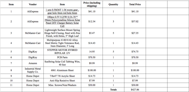
Cost Report
Concluding Thoughts
Lessons Learned
- Being the project manager helped me learn a lot about group and project management. Because this project is an integrated project with the Thursday class, it was very difficult to coordinate meeting times together or even contact the other group, therefore our project would fall back at times.
- It is hard to manage the conflicts among cost, schedule and performance. Our pathfinder team was having trouble on getting all the parts we wanted on time. Because we were short on time, there were sacrifices we had to make in terms of which parts of the project we wanted to get working depending on how many requirements it could fulfill.
- I learned too late that I should be stricter on tasks I wanted to get done to keep the project on schedule.
Resources
[1] Project Video
[2] Critical Design Review (CDR)
[3] Preliminary Design Review (PDR)
[4] Project Schedule
[5] Verification and Validation Documents
[10] Bill of Materials
[11] Final Interface Control Document (dated 12/13/16)
References
[1] Spirit Rover Cleaned: https://commons.wikimedia.org/wiki/File:Spirit_Rover_Cleaned.jpg