Fall 2016 Solar Panels: Software Block Diagram Update
By Stephan Khamis (Mission, Systems, and Test)
Approved by Inna Echual (Project Manager)
Table of Contents
Introduction
This blog post contains our most up-to-date software block diagram (SBD) for the Solar Panel system of the Pathfinder project. Within this blog post you will learn about the changes we have made since the CDR to update this diagram to reflect our design.
Previous Software Block Diagram

Figure 1: Software Block Diagram Presented During CDR
The software block diagram the group presented during our CDR presentation is shown in Figure 1. The group received feedback from the Missions, System, and Test division manager, president, and the customer that the SBD lacked details of our system and was missing key parts of our software design. As a result, the necessary changes were made to define our current Software Block Diagram.
Updated Software Block Diagram
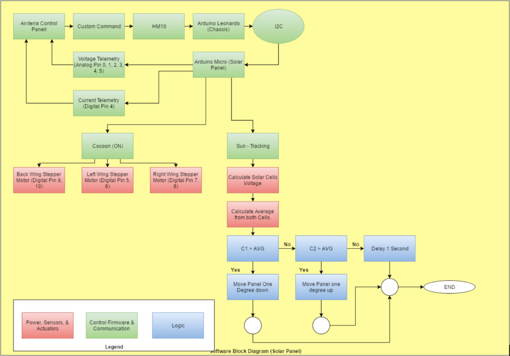
 Figure 2: Updated Software Block Diagram
The software block diagram in Figure 2 is the aforementioned update and it explains an overall understanding of what the Solar Panel systems software entails. It also includes a portion of the Chassis system and how we are interfacing with one another electronically, along with a legend on the bottom left to help detect what the different colors mean.
The Arduino Leonardo from the Chassis will be set as the master and connected to the Arxterra Control Panel. The Arduino Micro from our system will be set as the slave. The roles of each Arduino is as follows: the Chassis system will be sending the Solar Panel system custom commands (cocooning) and an autonomous command (sun-tracking). This will be done through an HM-10 BLE Bluetooth to an Android phone provided by the Chassis group. While the Chassis group is supplying us with Commands, we will then be supplying the Chassis with custom telemetry, such as current and voltage readings. The current readings will be provided from a current sensor that is pinned to digital pin 4 on the Arduino Micro. The solar cells will provide the voltage telemetry. This is done by connecting the solar cells outputs to Analog Pins 0, 1, 2, 3, 4, and 5.
Furthermore, the commands for the Solar Panels will be heavily communicating with the stepper motors. As you can see above, when the Cocoon command is switched on, it will then activate all three stepper motors. These stepper motors are connected to Digital Pins 5 and 6 for the left wing, Digital Pins 7 and 8 for the right wing, and Digital Pins 9 and 10 for the back wing.
The Sun – Tracking command, is autonomous and will always be running through a loop that is explained within the diagram. In simple terms, the program will compare the voltage readings through the solar cells on the left and right wings. For the wing with the greater voltage, the wings will then adjust itself to that direction of the sun.
Future Updates
As of now, there are no future updates that I plan to change within the now updated Software Block Diagram.
References
[1] Arduino MICRO and Genuino MICRO Reference: https://www.arduino.cc/en/Main/ArduinoBoardMicro
[2] Arduino Leonardo: https://www.arduino.cc/en/Main/ArduinoBoardLeonardo
[3] Fall 2016 Solar Panels: 12C Communication Experiement: http://arxterra.com/fall-2016-solar-panels-i2c-communication-experiment/