Fall 2016 Velociraptor (W): Hardware Design
By Aaron Choi (Manufacturing Engineer)
Approved by
-Lam Nguyen (Project Manager)
-Tim Haddadian (Division Manager for Manufacturing )
Table of Contents
Requirements
Level 1-2 requirement states that the Velociraptor budget shall not cost more than $102.
Level 2-1 The center of gravity on axis of legs shall be controlled by one servo. The head and tail shall not exceed [data to be calculated] degrees in order to avoid the robot from tipping over.
Level 2-3 The Velociraptor shall have two legs mechanism [Theo Jansen or UCI] in standing position to support the mass of robot with 50% margin.
Level 2-4 The Velociraptor should control the center of gravity on the axis of the H/T should be controlled by one servo.
Level 2-7 The Velociraptor shall have a foot design that uses [springs or struts] to maintain foot angle at minimum 6.5 degrees when not in contact with ground.
Introduction
For the Wednesday Velociraptor, the Theo Jansen leg mechanism shall be implemented to meet the Level 2-3 requirement. For the materials utilized, Birchwood is chosen to fulfill the Level 1-2 requirement and based off trade-off studies- [1].
Design
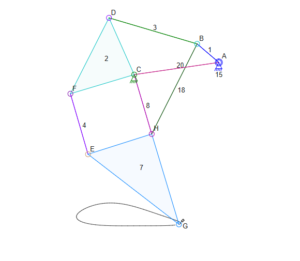
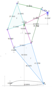
For the design, a simple CAD program called Linkage was used to model the walking path of the design. The CAD program, created by David Rector, allows users to design two dimensional mechanisms and simulate the movement of those mechanisms [2]. From this CAD program, the Jensen leg mechanism were used to model and observe the walking path. Linkage allowed users to adjust the lengths of each linkage. From experimenting the lengths, the finalized leg design for the Velociraptor was chosen. This design was chosen to increase the vertical height of the legs while maintaining the walking motion.
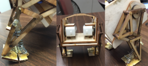
Figure [1]
The figure above shows the Theo Jensen leg mechanism.
Figure [2]
The figure above shows the design used for the Wednesday Velociraptor.
PDR Demonstration
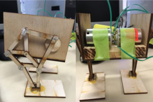
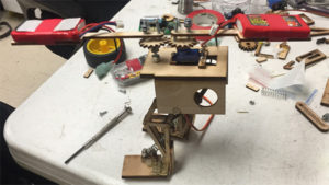
Figure [3] shows the design that was presented for the Preliminary Design Review demonstration. This design did not contain a head and tail, however the Theo Jansen leg mechanism was implemented.
Figure [3]
The design presented for PDR.
Some issues occurred during demonstration. The DC motors used did not provide enough torque for the Velociraptor to walk. The shaft of the DC motor constantly slipped in the shaft of the rotation piece of the Velociraptor. The linkages were not stable enough. To fix the unstable linkages, another linkage parallel will be added.
CDR Demonstration
Figure [4] shows the design that was presented during the Critical Design Review presentation. The outer shell, foot design with toe joint, and head and tail were included into this design. The DC motors used were the GM9, which were chosen from trade-off studies from Taylor Farr. The HS-322HD servo was used to control the head and tail. The servo installed was to fulfill the Level 2-1 requirement. An outer shell was implemented for a see-saw design for the Velociraptor to shift the mass forward when walking on incline. This would balance the robot when walking on incline surfaces. To control the platform, a servo will be implemented which meets the Level 2-3 requirement. The passive toe joint was used based off research [3] and to meet the Level 2-7 requirement. The ankle of the foot was positioned at the tip of the triangle for the leg. This helped match the walking motion of the Velociraptor. The additional linkages were able to stabilize the links unlike the PDR model. This improved the balance of the robot with stable legs.
Figure [4]
The body design presented for CDR.
Figure [5]
The leg and foot design presented for CDR
The model failed to walk without falling backward or forward. The head and tail were unable to move due coding. A solution given by Professor Hill was to move the GM9 motors on the outside. This was to ensure that the center of mass would be directly over the foot for the Velociraptor.
CDR Demonstration 2.0
Figure [6] shows the design that was presented for the Post CDR demonstration The GM9 motors were moved to the outside to shift the center of mass easier. The feet length of the robot were also increased to increase the surface area of contact. An issue with the previous design was that as the robot walks, the ankle at which it walks did not match the walking motion of the robot. Rather than using the HS-322HD servo, the SG90 servo was installed.
Figure [6]
The body design presented for Post CDR demonstration.
When presenting the design, the robot could not walk forward without balancing by itself. One addition that would be able to solve this issue is add traction material to the bottom of the foot. The spring of the toe joint was unable to support the mass of the robot, causing the robot to fall when balancing. To resolve this, further experimenting with springs will be carried out.
Game Arena Design
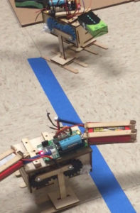
Due to time constraints, Paul Ahumada’s physical model was implemented for the Game Arena and test plans. For this design, a body was used that could utilize both Ahumada’s design, and the Velociraptor leg design. Ahumada’s design revolved around using gear trains to rotate the leg.
Figure [7]
The top robot is the Thursday Velociraptor. The bottom robot is the Wednesday Velociraptor.
Post Game Arena Design
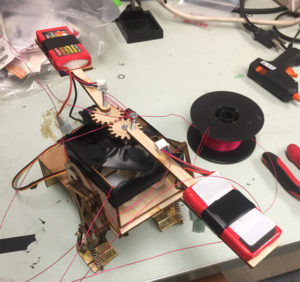
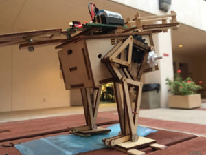
Figure [8] below shows the design shown to the customer after the Game Arena and Validation plan was finished. The Jansen linkage installed onto the body of Ahumada’s design [4]. Although the Velociraptor could not statically walk without tipping over, the walking motion did show that the robot could move forward.
Figure [8]
The design with the modified Theo Jansen linkage.
Conclusion
The hardware prototypes implemented subsystem designs which derived from the level 1 and level 2 requirements. The issues that were faced were due to center of mass. The Velociraptor could not balance well due to the center of mass. Additionally, the body would continuously sway. A possible solution would adding an additional linkage that attaches from the body to the rotation shaft of the motor that would help stabilize the robot.
References:
[1]http://arxterra.com/material-trade-off-study/ [2] http://blog.rectorsquid.com/linkage-mechanism-designer-and-simulator/[3]http://ocean.kisti.re.kr/downfile/volume/icase/JOJDCV/2011/v17n7/JOJDCV_2011_v17n7_659.pdf [4] http://arxterra.com/mechanical-design/

