Fall 2016 Velociraptor (W): System Block Diagram
By: Gifty Sackey (Mission, System and Test Engineer)
Approved by:
– Lam Nguyen (Project Manager)
– James Lee (Division Manager for Mission, System and Test)
Table of Contents
Introduction
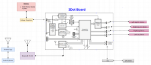
The system block diagram describes how all the signals connect to all the components and communicate with the 3DoT board. Aside from the 3DoT board, which was provided by Professor Hill, there is an external PCB which is designed by the electronics and controls engineer and fabricated by the manufacturing engineer. On the Velociraptor our shield will have a stepper motor drivers (A3901) for 2 stepper motors. These two devices are the linear actuators that will change the pattern of the step. For instance if the Velociraptor needs to go up an incline, it would be able to step higher and not hit its foot against the bottom of the incline. In order to have the stepper motor driver be compatible with the I2C interface, we will utilize a GPIO expander that is I2C compatible. The driver will control the linear actuators. The linear actuators will change the radius of the rotational movement which will change the motion of the leg movement.
Design 1
Diagram 1: First design for System Block Diagram
Design 2
In our final design of the System Block Diagram we had added a color scheme to the one below. Following from the external battery on the shield (external PCB layout) the colored lines indicates the voltage level before going stepping down in voltage for certain regions of the schematic. The orange lines indicate the 7.4V battery going through the LM7805 LDO. The blue line is connected to the 3DoT board which powers the 2 DC motors and the servos. The blue line also steps down again though the LDO on the 3Dot board dropping down to 3.3 V. This in part will power all of the sensors on the external PCB board.
Diagram 2: Finalized System Block Diagram
External Power Supply
The Velociraptor is required to participate in the end of semester game alongside with other robots. The Velociraptor will be designed to last a duration of the game which is 1 hour. Two external batteries will be used in addition to the battery power provided through the 3DoT board. The external battery of choice is the YPG 850mAh 7.4V 25C 2S Li-Po Battery which will be stepped down by the LM7805 LDO to 5V at 1.5 amps maximum. The output of the LDO is connected to the external battery connection on the 3DoT board.
Balance – IMU
Above the stepper motor connections are the legs of the Velociraptor (Figure 1). The orientation movement of the robot will be sensed by the IMU. The IMU is connected to the PCB via I2C interface and its purpose is to measure the angles and acceleration in x, y and z directions. By incorporating the IMU in our design, we are able to determine if the velociraptor is unbalanced. The control algorithm that will be implemented for the velociraptor will be a closed loop algorithm which is always checking against a calculated value that corresponds to the velociraptor’s balance.
Position Tracking – Rotary Sensor
The connections of the DC motors controlling the legs need to be connected to the rotary encoders. Since the rotary encoders are not I2C compatible, they require a connection to an A/D converter. In the case of the velociraptor, a 12-Bit ADC converter type of ADS1015 has been chosen.
Bluetooth Commands/Telemetry
The Arxterra Control Panel is made up of the controls that our software and firmware will be using to control the velociraptor. The velociraptor robot will be able to receive commands through two main modes, community mode(laptop) or remote control mode(phone). In the event that the velociraptor will be receiving commands from the android phone, the Arxterra app would need to be configured into a remote control mode to control the robot. The 3Dot board is embedded with an HM-10 Bluetooth module which aids the communication of the software to the robot. A software block diagram for the velociraptor can be viewed to gain a better understanding of the software controls for the velociraptor. This Bluetooth module is compatible with either an Android or Apple iPhone. Users are required to have a membership account with the Arxterra company in order to achieve this communication platform necessary to have the robot receive commands. For the velociraptor group, the goal is to modify the existing move command code in the 3DoT library and in turn have the velociraptor be able to turn left, turn right, walk up and down inclines and lastly statically walk.
Embedded in the 3DoT board is a TB6612FNG motor driver which will be needed to drive two GM9 motors that will be used to control the legs. Each motor will be attached to each leg mechanism of the robot. The motor driver’s purpose is to receive low current control signals from the 3DoT board and output a higher current signals. These signals can drive the motors that move the legs.
Conclusion
In the end the first thing we needed to consider was how much torque we needed to move our robot. Once we had the mass figured out we could determine the amount of current needed to power the robot. After that we account for all of the actuators, sensors, and other electronic devices so that our robot is fully functional. If our design changes then


