Pathfinder Solar Array Fall 2018
Solar Array Amperage Testing
Author/s: David Born
Table of Contents
Introduction
An experiment to determine the max amperage through the solar array system was performed.The experiment made sure to test at several elevation and azimuth points to maximize the current. The elevation and azimuth of the Sun were also recorded during the experiment. This was needed to figure out the wire gauge for the headers, trace width on the PCBs, and the amount of solar cells required to charge our 12V battery. The solar cells, model 80X55, from the past semesters were reused.
Sunny and Cloudy
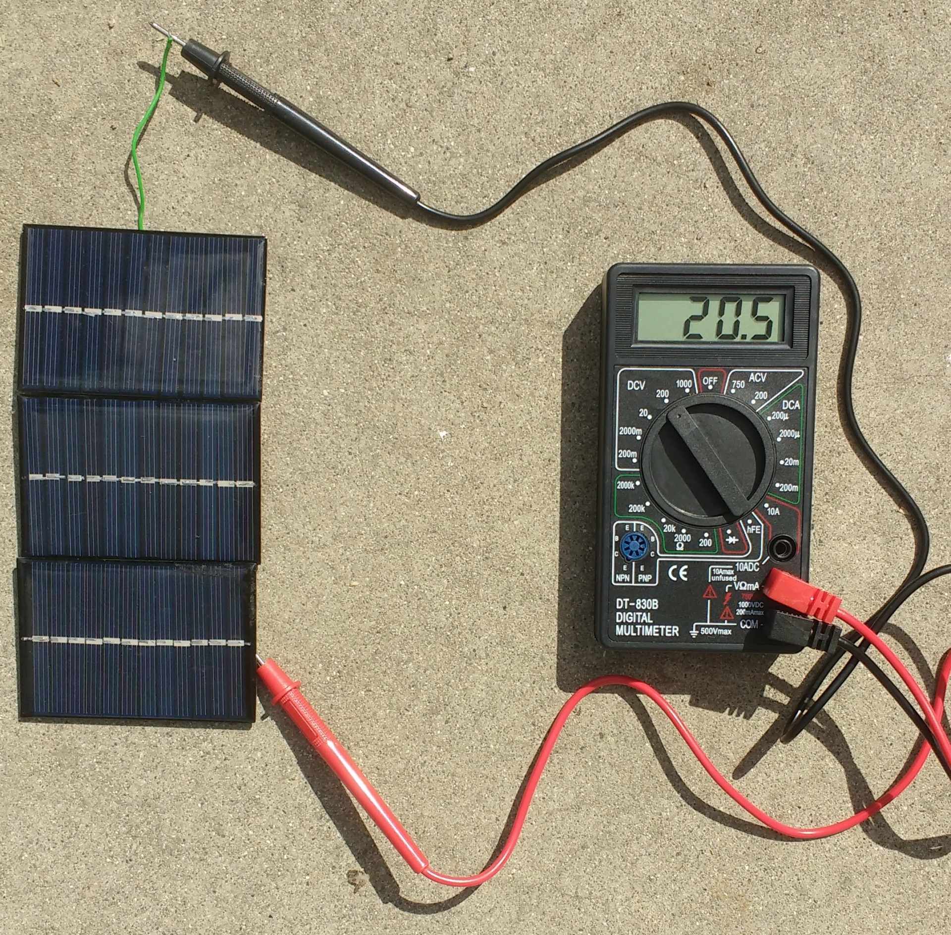
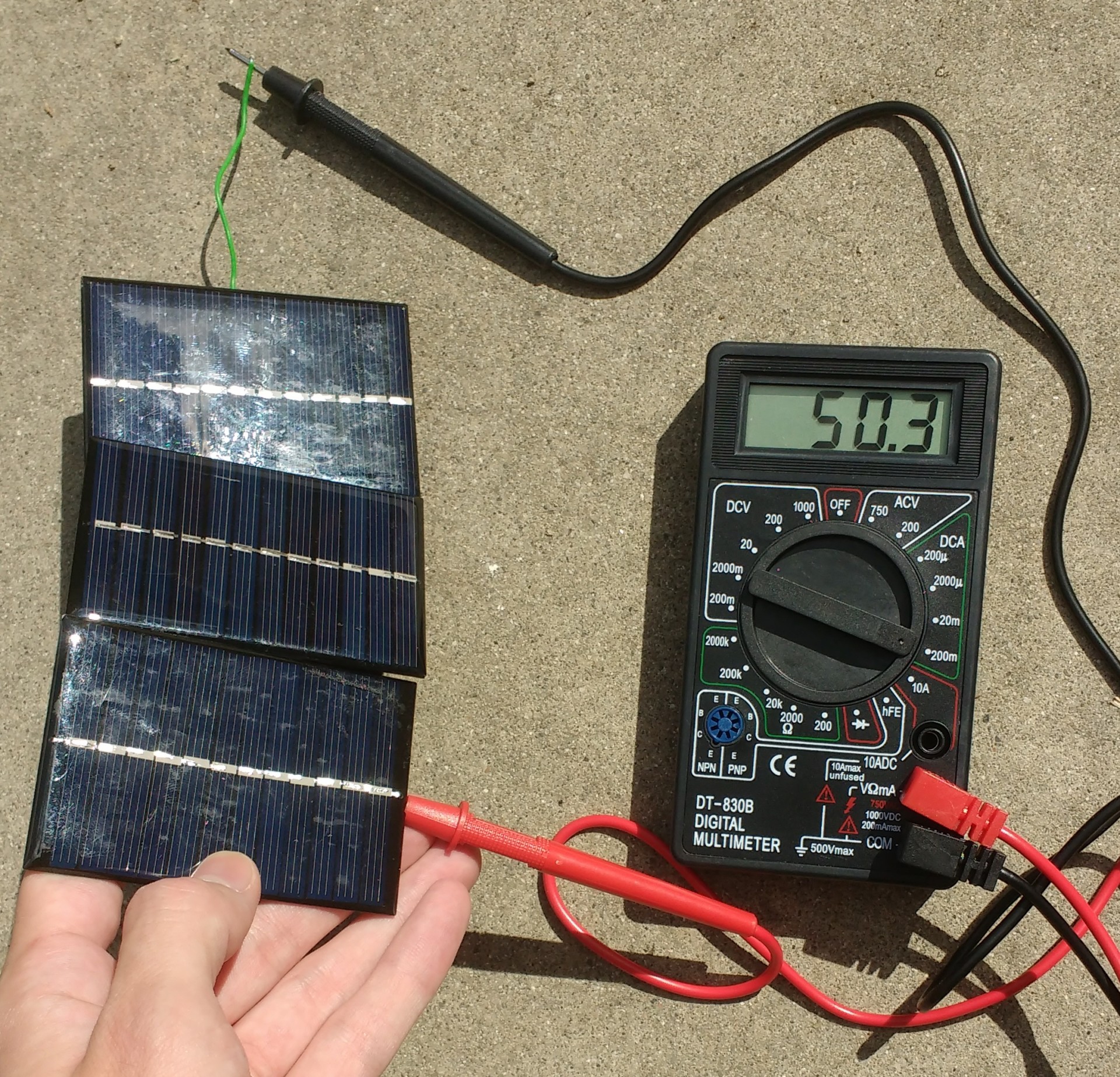
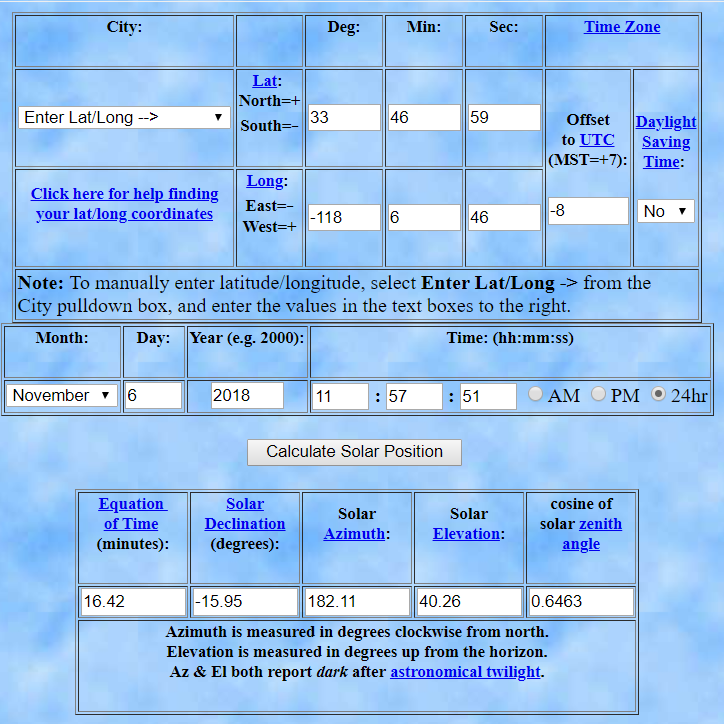
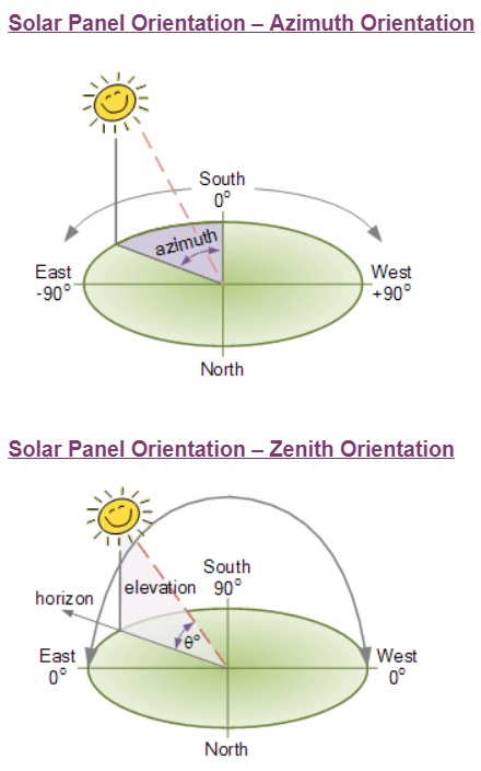
The experiment was performed both on a sunny day and a cloudy day to ensure that the battery would charge in both situations. A single module of three solar panels were connected in series. The panels were left in natural light. Artificial light doesn’t have enough power for accurate results. The open circuit voltage and closed circuit current are recorded in table 1 for sunny day results. Figure 1 shows the experiment when the power generated was max, Azimuth 185o and Zenith 400. Figure 2 shows the experiment when the panel was laid flat on the ground, Azimuth 185o and Zenith 90o. The experiment was done on November 6, 2018 at 11:57AM. Figure 3 shows a screenshot of an online calculator telling the Sun’s position at that time. Figure 4 is a screenshot to help with understanding Azimuth and Zenith3.
| Azimuth (Degrees) | Zenith (Degrees) | Voltage (V) | Current (mA) |
| 185 | 90 | 20.5 | 37.8 |
| 185 | 60 | 27.2 | 45.7 |
| 185 | 40 | 30 | 50.3 |
| 185 | 30 | 28.7 | 48.6 |
| 185 | 0 | 21.2 | 26.5 |
| 185 | -30 | 20.2 | 9.4 |
| 155 | 40 | 26.1 | 43.4 |
| 215 | 40 | 26.9 | 44.7 |
| 5 | 40 | 18.3 | 6.1 |
On a Cloudy day the 3-Cell Module was consistently 17.5V and 5.3mA despite changes in azimuth and zenith.
When a phone LED light was shone directly module, the 3-Cell Module produced a maximum of 13V/0.6mA.
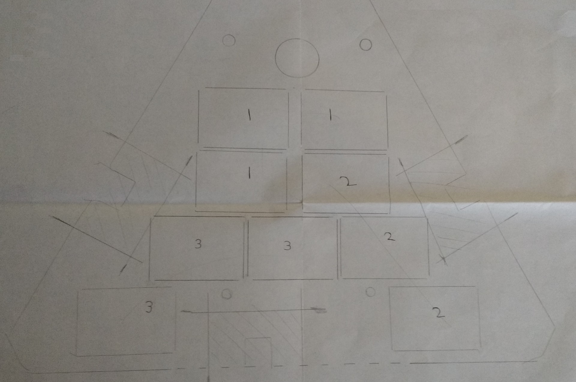
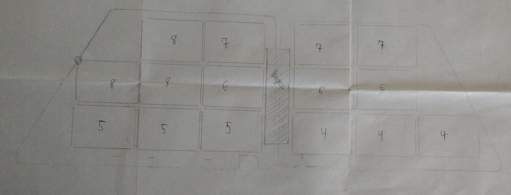
Solar Panel Layout
Conclusion
It was interesting to find that most artificial light wouldn’t give nearly the same amount of power as natural light. There are many online sites that will calculate the required trace width from the required current. Remember that PCBs in America use mils (thousandths of an inch) as the standard unit of distance measurement. It may be possible to use only two solar panels per module but then we wouldn’t be able to charge the battery on cloudy days.

