ModWheels
Author/s: Kordell Tan (Project Manager)
Uzziah J. Lontok (Manufacturing Engineer)
David Zhou (Electronics & Control Engineer)
Verification:
Approval:
Table of Contents
Executive Summary
The Fall 2019 ModWheels toy car is a fresh new take on the modern customizable robot car. Inspired by the dimensions of the Kidstuff 50th Anniversary ’67 Red Chevy Camaro SS 327 cardboard car model, this robot car comes fully integrated within the Arxterra suite of applications, implementing both custom lighting features and digital sounds in solidarity with the car model that can be controlled via Arxterra Mobile App. This generation of the robot car aims to implement an adaptive speed control to traverse a dynamic track.
Program and Project Objectives
Project Objectives
The ModWheels Generation 3 robot is a laser-cut, mobile-controlled toy car with steering capabilities that is able to maintain constant velocity as it travels across different surface grades on a specified path. This toy car simulates a real car, mimicking model car dimensions with a fully functioning lighting system, differential turning system, and digital sound system, while integrating its processes using a 3DoT V9 Board that is fully compatibly with the Arxterra Mobile Application.
Mission Profile
The Fall of 2019 ModWheels will demonstrate constant velocity by traversing across pond bridge at the CSULB Japanese Garden while being controlled via Arxterra Mobile Application, while operating with headlights and turn signals.
Project Features
- Bluetooth Remote Control via Arxterra Mobile App
- Operates using a 3DoT v9 Board
- Programmable Speaker Signal for Custom Horn/Start-Up Song with Adjustable Volume
- Differential Turning
- Access to Power Switch and USB Port from accessible door
- Fully laser-cut wood chassis with easy assembly
- Adaptive Speed Control
- Brake Features
Requirements
Engineering Standards and Constraints
We are in compliance with constraints on the project imposed by The Robot Company (i.e., CSULB) and Project Stakeholders. Specifically, we include University and applicable environmental, health, and safety standards and those safety standards specifically associated with the product (e.g., Children’s Toys).
Applicable Engineering Standards
ATmega16U4/ATmega32U4, 8-bit Microcontroller with 16/32K bytes of ISP Flash and USB Controller datasheet section datasheet, Section 18, USART
Bluetooth Special Interest Group (SIG) Standard (supersedes IEEE 802.15.1)
C++ standard (ISO/IEC 14882:1998) – Arduino De Facto Standard
American Wire Gauge (AWG) Standard
USB 2.0 Specification released on April 27, 2000
NXP Semiconductor, UM10204, I2C-bus specification and user manual
Motorola’s SPI Block Guide V03.06
Environmental, Health, and Safety (EH&S) Standards
All Safety regulations as defined in Section 4.3 Hazards and Failure Analysis of this document shall apply to the shipping, handling, storage, and disposal of LiPo batteries.
IEEE National Electrical Safety Code (NESC)
ASTM F963-17, The Standard Consumer Safety Specification for Toy Safety
CSULB Physical Planning & Facilities Management (PPFM) Environmental Compliance Electronic Waste Handling and Disposal Procedures. These procedures shall be followed for the disposal of all batteries
The National Institute for Occupational Safety and Health (NIOSH) Electrical Safety [1998][page 8]
Program Level 1 Requirements
L1.1 Product will implement a 3DoT V9 board as its main processor.
L1.2 Product shall use a speaker to create sounds.
L1.5 Product shall be in compliance with the 3DoT Command and Telemetry Packet specifications.
L1.9 Product shall be constrained to a cost not to exceed $250.
L1.10 Product will be constrained to a completion date of December 17, 2019; this includes documentation, materials, and reports.
L1.12 Product shall be constrained to a disassembly and reassembly time of 20 minutes.
L1.14 Product electornics enclosure shall be constrained to be no greater than the 3DoT board, shields, and mounting hardware.
L1.15 Product will be powered by a 3.7V RCR123A battery included with the 3DoT board or use of the external battery 2.omm PH series JST connector located on the 3DoT board.
Project Level 1 Functional Requirements
Level 1 requirements define the general tasks that the robot should perform to achieve its objective.
L1.3 Product shall be able to use the Kidstuff 50th Anniversary ’67 Red Chevy Camaro SS 327 paper car model as its exterior shell.
L1.4 Product shall be controlled via Bluetooth 4.0 in compliance with the Bluetooth Special Interest Group (SIG) Standard (supersedes IEEE 802.15.1).
L1.6 Product shall have headlights and turn blinkers.
L1.7 Product shall be able to maintain a constant velocity.
L1.8 Product shall have steering capabilities.
L1.11 Product shall be constrained to a disassembly and reassembly time of 20 minutes.
L1.13 Product shall have immediate access to external connectors and switches.
System/Subsystem/Specifications Level 2 Requirements
The level 2 requirements provides design solutions to achieve level 1 requirements.
L2.1.1 Product will be driven using two machine gear motors.
L2.2.2 Product should incorporate a limited slip differential to maintain stability in uneven terrain.
L2.2.1 Product shall generate custom car sounds, such as a car horn or reverse alarm sounds between 200 Hz and 2000 Hz.
L2.3.1 Product components will fit a box dimesion of 185x75x45 mm.
L2.3.2 Product should have a custom 3D printed shell with box dimensions with 5% of 185x75x45 mm.
L2.4.1 Product will utilize an HM-11 board to establish Bluetooth connectivity.
L2.4.2 Product will be operated using the ArxRobot app on a smartphone or a similar mobile device.
L2.5.1 Product will use C++ and Arxterra Robot Libraries within the Arduino IDE to control motor drive, blinker, and turning.
L2.7.1 Product shall be able to maintain constant velocity at a maximum incline or decline of 12 degrees.
L2.7.2 Product shall maintain constant velocity while traversing the 97.53 m outer path of the CSULB Japanese Garden.
L2.8.1 Product shall use a servo that will have a turn angle range of 20 degrees.
L2.8.2 Product shall incorporate an electronic differential to the rear wheel motors for rotational compensation.
L2.11.1 Product shall maintain full form and functionality after a 14 meter drop test is performed on it.
L2.12.1 Product shall include the use of LEDs and a speaker for added car features.
L2.13.1 Product disassembly time shall be 10 minutes.
L2.13.2 Product assembly time shall be 10 minutes.
L2.17.1 Product shall be driven using two 6V machine gear motors.
L2.17.2 Product shall use a SG90 servo for turning.
Allocated Requirements / System Resource Reports
Project Report
This section contains the work breakdown structure, product breakdown structure, budget, and schedule for the Fall 2019 ModWheels project.
Project WBS and PBS
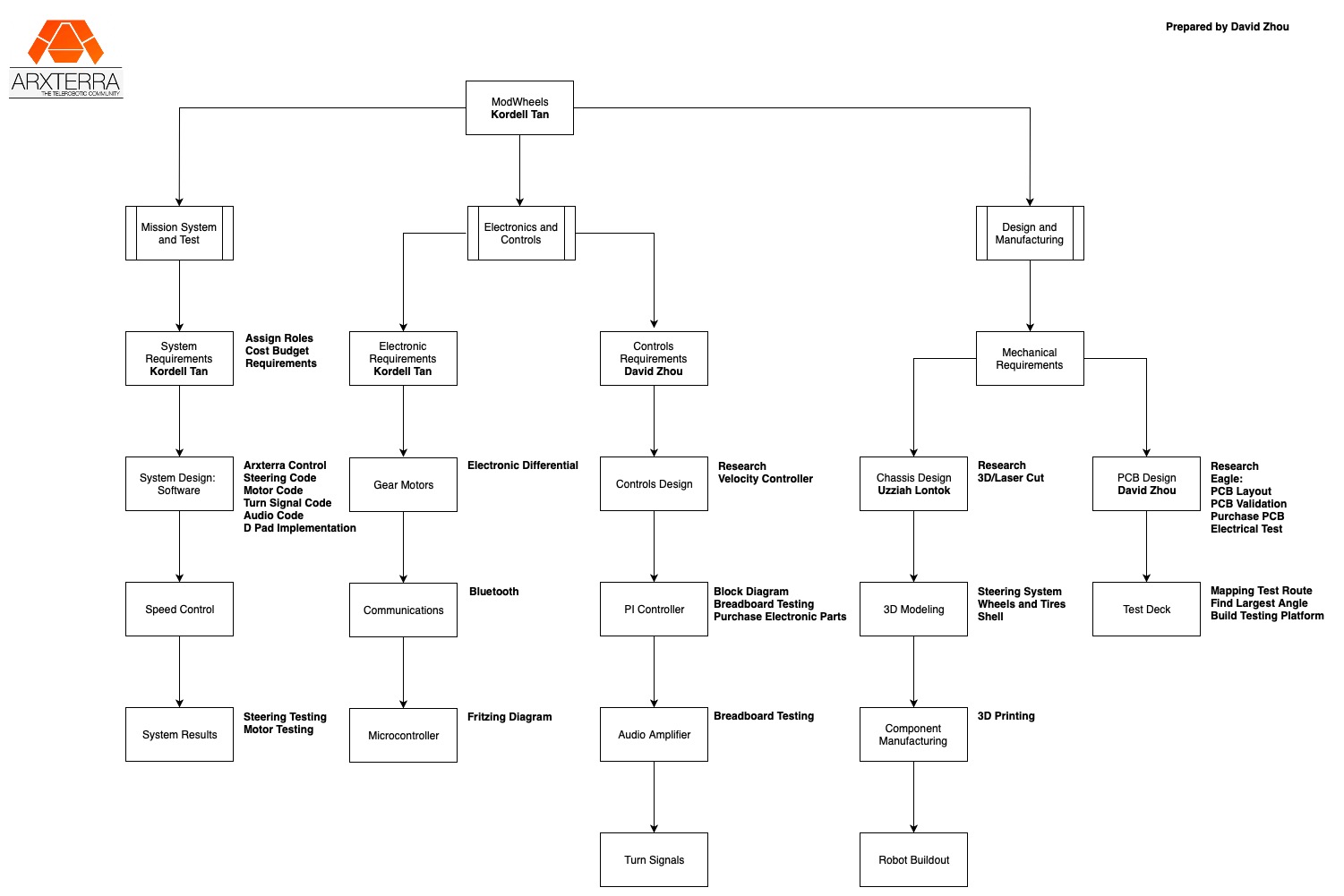
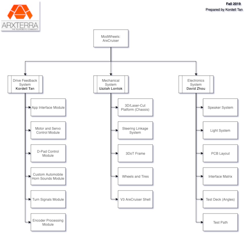
The work breakdown structure shows the different tasks that were needed to complete the ModWheels project and the person responsible for delivering each task.
The product breakdown structure shows the items needed in order for ModWheels to be able to function and the person responsible for delivering those specified items.
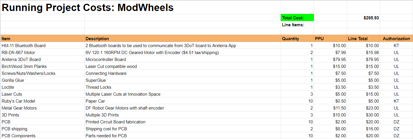
Cost
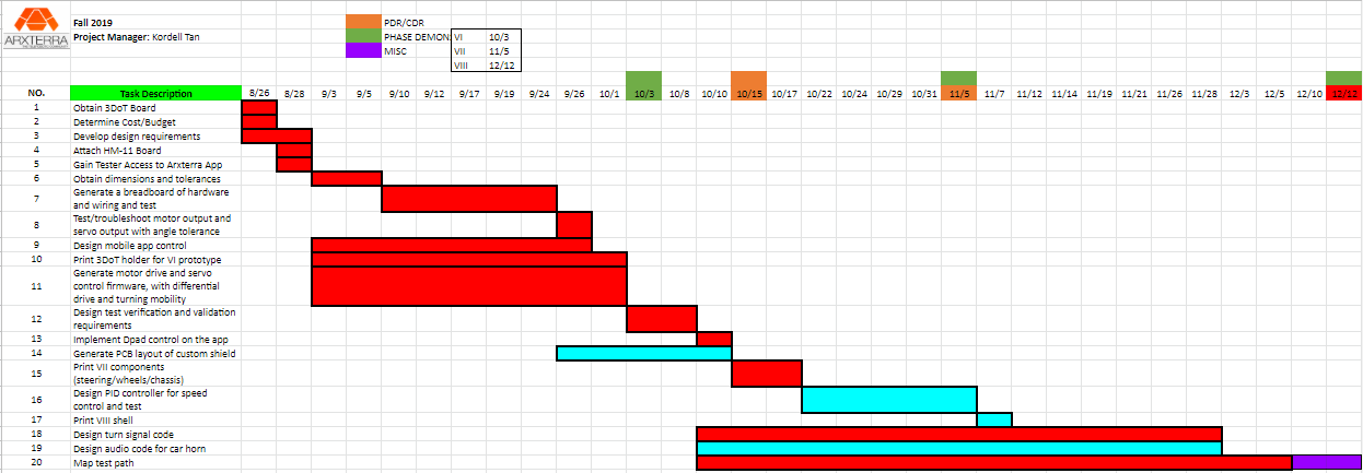
Schedule
Summarize schedule status including percentage complete and if available a burn down diagram.
Concept and Preliminary Design
Generation 3 of ModWheels was designed to simulate a Camaro with cruise control. Implementation of the speaker, LEDs, and drive train features were inspired by the operation of a real-life car. A main challenge was implementing several simple features that could be handled all at once without dragging the clock and pointer of the processor.
Design Innovation
This project seeks to implement these new innovations:
- I2C read and write to control slave devices
- Laser-cut dimensions for custom chassis design
- The development of custom tires and wheels using modeling
- Testing methods for 3DoT current-limiting features and motor drive
- Velocity control and speed compensation using a digital PI controller (failed)
Conceptual Design / Proposed Solution
The main functionality of this project centers around the processors ability to juggle multiple services at once. It is recommended to use interrupt service routines to trigger the activation of these conditions. Considering all of the small systems within the scope of the project, we were faced with a dimensional constraint (with having to fit everything within the Kidstuff Car), so utilizing more code and more digital components to assist in the succession of each requirement is important in saving physical space.
System Design / Final Design and Results
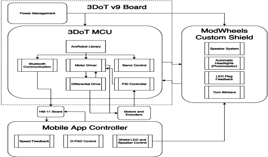
System Block Diagram
Interface Definition
Mission Command and Control
3DoT Robots
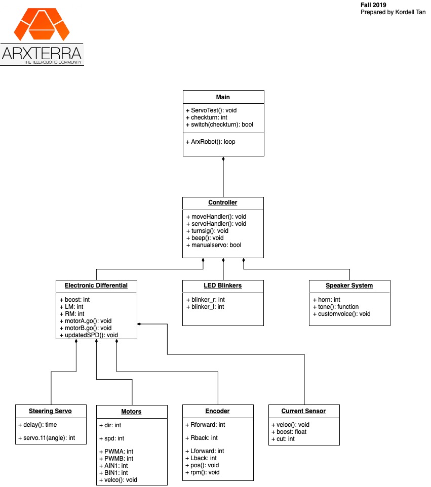
This section provides a systems level look at the software modules employed by 3DoT robots. This section represents a collaborative effort by the system and electronics/control engineers.
| Hardware | Software |
| Personal Computer | Arxterra Control Panel |
| Smartphone | ArxRobot App |
| 3DoT Board | Arduino and Robot3DoT Library |
The above software block diagram shows how the code structure is implemented to maintained all major features of the robot car. The code relies heavily on the 3DoT “doing something” when a code (hex packet) is received from the mobile app. In the firmware, we see that the easiest way to manage all the features while not delaying the clock can be to use flags to trigger certain systems.
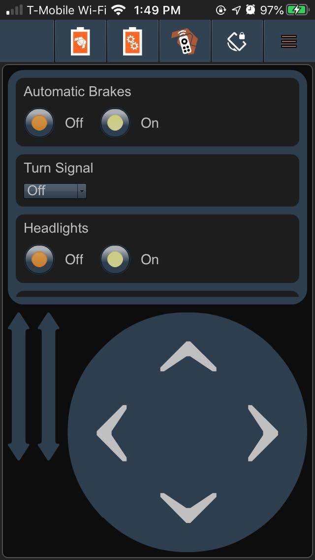
Here is an initial look on the custom app interface used to control the actions and systems implemented by the ModWheels project.
Electronic Design
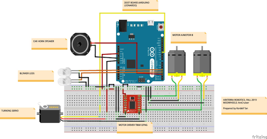
The figure above is a fritzing diagram of our electrical system. The 3DoT has been replace with an Arduino in the diagram due to parts constraints in the fritzing program. Through this diagram you can see the placement of the LEDs and the speaker. All components have been tested through actual breadboarding.
PCB Design
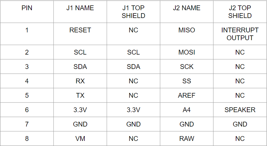
The third generation ModWheels Custom PCB includes an onboard audio amplifier, and I2C GPIO expander IC to accommodate multiple devices, a speaker, and LEDs that will be used as headlights and turn blinkers. In this section we will discuss the design of the custom PCB and the IC chips used in the PCB. The link below will lead to the blogpost that will discuss the design in more detail.
Note that the major features supported by the system populating the PCB include an audio amplifier for the speaker, an LED bank and encoder inputs ported to the I/O pins of the I2C GPIO Expander IC.
Firmware
ModWheels Fall 2019 software implements differential drive, motor control using the onboard motor driver, servo control utilizing the dedicated servo pins, I2C expansion access of the custom PCB shield to control headlights and turn blinkers, and speaker control.
Mechanical/Hardware Design
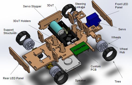
During this design process for this ModWheels generation, we worked with a few different types of chassis design: one fully 3D-printed, with a 3DoT holder and 3D-printed steering linkage system, a fully laser wood-cut chassis with puzzle-piece assembly, and one hybrid chassis that incorporated a wooden laser-cut chassis and a 3D-printed 3DoT harness. We use flexible Polyjet Tango to print the tires of the wheels. The dimensions of our enclosure were designed to fit within a Kidstuff cardboard car model.
Verification & Validation Test Plan
Our test verification and validation plan allows us to confirm support of the success of project requirements. This semester’s project performed really well compared to the stated Level I project requirements.
Concluding Thoughts and Future Work
The biggest roadblock to this ModWheels project is the accumulation of all of the small features that are being added to its structure. Each individual feature on it’s own is not such a daunting task, but to generate a program that can handle all of the functions and subroutines to operate all of these events without cluttering the clock and optimized for fast response becomes a difficult task. It is recommended to use interrupt subroutines and multi-feature functions to handle the wide variety of tasks that can be presented with this project.
References/Resources
These are the starting resource files for the next generation of robots.

