Fall Biped 2016- Ankle Stress Test
By: Hector Martinez (Manufacturing Engineer)
Approved by: Ijya Karki (Project Manager)
Table of Contents
Introduction
Requirement
“Shall be able to turn up to 180 degrees on each of its sides.”
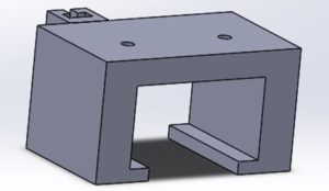
In the COM Blog Post , I discussed the leg design inspired by the Theo Jansen Biped (TJB) which uses cleverly designed linkages and shafts to shift center of mass (COM) and facilitate walking. One of our requirements is that the biped is able to turn but the TJB does not allow for turning, to overcome this issue, we are adding servos to the bottom of the TJB foot which will allow our biped to turn. In order to attach a servo to the TJB foot, I designed a custom servo housing that will act as an ankle.
Fig. 1 – Custom servo housing that will screw directly to the TJB foot.
Once the servo is mounted, a new custom foot will be attached to the servo that will act as our new foot. This new foot will also serve as a housing for our color sensor which will go on the bottom of the foot. This color sensor is due to requirement that we must detect color pads that will be scattered on the playing field. In order to attach a new foot to the servo, a servo horn will be used that will be screwed to the foot.
Ankle Design
Fig. 2 – TJB foot with ankle (servo housing), servo, and new foot attached.
One concern for the ankle and the reason for this blog post is the structural integrity of the ankle while the weight of the biped rests on it. When the biped takes a step, all the weight of the biped will rest on the housing and we are worried that the ankle may fracture or break. One of our requirements is that the biped should weigh no more than 750 grams. An easy and efficient way to test the ankle at this weight is to use SolidWorks. By simulating on SolidWorks we can get a good idea of the type of stress the ankle will handle. In order to perform a proper stress test, a material, load, load direction and fixture must be set on the part.
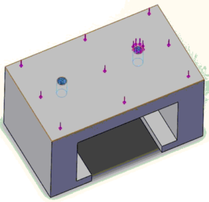
Fig. 3 – Fixtures and load direction specified on the ankle.
The image above shows the direction of the load (purper arrows). Obvisously, the weight of the biped will only cause a vertical load on the ankle, which is set to our maximum possible weight of 750 grams. The material specified is ABS plastic. A fixture is specified at places that cannot or should not move, in the case of the ankle, fixtures are set at the mounting holes to the foot (blue arrows). When the simulation is run, these fixtures will act as rigid bodies which may be subject to break or fracture.
Conclusion
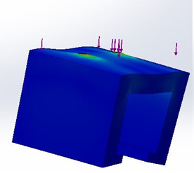
Fig. 4 – Different angles of stress analysis of ankle.
The image above shows the results of the stress analysis. The results show where and how a part may fail. The blue color indicates the ankle undergoing limited stress while red indicates heavy stress and possible failure. In the case of the ankle, there is more stress at the fixture points, but based on the color scale, the ankle is able to support this load. The simulation also shows how the ankle may warp due to the load, but this does not mean this is how the ankle will warp. Additionally, the simulation assumes that the inside of the ankle is empty. Obviously with a servo sitting inside the ankle, this kind of warping will not be possible. Based on the results of the simulation we are confident that this ankle will be able to support the maximum allowed weight of 750 grams.


