Fall Biped 2016- Shifting Center of Mass to Achieve Walking
By: Hector Martinez (Manufacturing Engineer)
Approved by: Ijya Karki (Project Manager)
Introduction
Requirement
“Shall be able to walk a minimum speed of 0.32 mm/sec.”
A proper biped design must implement a weight shifting mechanism that allows for walking. This is because walking requires the weight of the object to be shifted to one foot so the free foot can be swung forward and repeat the process(1). The group responsible for the Velociraptor found a Theo Jansen inspired biped toy which implements a unique walking mechanism that integrates a swinging leg with a weight shifting ankle.
Process of Design
Fig. 1 – Packaging of Theo Jansen inspired biped, one propeller and ball bearings create walking.
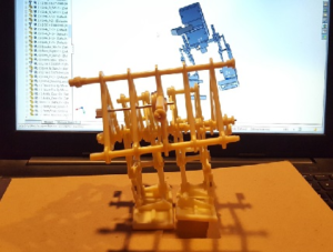
The biped toy uses on motor, ball bearings, and a cleverly designed shaft to control both weight shifting and walking. We believe we can benefit from this design because one of our requirements states that our walking must be done with one motor. Other bipeds have implemented walking and weight shifting with two different mechanisms, some of the mechanisms to shift weight includes motorized hips, motorized knees, or weighted motorized arms, but these designs require multiple motors and servos. The simplicity of the Theo Jansen Biped (TJB) allows us to kill two birds with one stone.
Fig. 2 – Assembled biped toy with fan removed, shaft and links provide mechanism to walk/shift weight.
The design that we presented for CDR implemented Theo Jansen legs and used weighted motorized arms to shift weight. Through simulation on SolidWorks, we discovered that the width of our feet required an absurd amount of weight (1.5 kg) at the arms to shift the Center of Mass (COM) to allow for walking. It was after CDR that we realized that two things had to change with our design: 1) our legs needed to be much closer together, like the picture above, and 2) the biped needed something more than arms to assist with weight shifting.
Fig. 3 – CDR design. Checkered circle shows where COM is located when arm is extended.
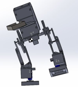
After realizing that the TJB toy implements weight shifting and walking in one mechanism, we decided to implement it to our design. Our design features a scaled version of the TJB along with “arms” which hold a battery tray. This battery tray is attached to a servo which will turn left and right on the horizontal plane, this will help us mimic the ball bearings the TJB uses to assist with weight shifting.
Conclusion
Fig. 4 – Final design. Linkages and battery tray allow the COM to be centered over the foot.
Additionally, the smaller gearbox allowed us to shorten the width of our chassis from 60 mm to 40 mm which directly shortened the width of our feet. As the picture above shows, the linkages allow the biped to use its feet as anchors, with a proper motor shaft design, these allow the entire biped to lean. Thus, this allows its COM to shift over the foot and allows the other foot to take a step. By turning the arms and battery tray, we mimic the ball bearings the TJB uses to allow for extra stability while taking a step.


