Goliath Fall 2016
Final Design
By: Dylan Hong (Design and Manufacturing Engineer)
Approved by Kristen Oduca (Project Manager)
Table of Contents
Introuction
Requirement:
- The Goliath shall be a scale model of the Goliath 302 tank.
- The Goliath should have an approximate ratio of 1 : 0.566 : 0.373.
- Goliath shall house the 3Dot Board, sensors, and custom PCB.
- The Goliath will have a total of two gears in the front, two driving wheels in the rear side, and fourteen wheels in the center.
- Goliath shall house the 3Dot Board, sensors, and custom PCB.
- The Goliath should have an approximate ratio of 1 : 0.566 : 0.373.
After going through many iterations of the design process to meet functionality and the requirements, we were able to finalize the design of the Goliath. Most of the changes that were made were considered to be tweaks but were necessary to achieve functionality of the tracks, sensors and appearance of the Goliath.
Final Body Dimensions
After many iterations of redesigning the chassis dimensions, we were able find the right dimensions to fit all the necessary components while making it functional. The final dimensions were measured at 4.71 x 3.77 x 1.8 inches. When compared to the previous dimension of 4.27 x 2.94 x1.5 inches, the final dimensions were increased by 0.44 x 0.83 x 0.3 inches. This increase was necessary because we decided to use the prefabricated Tamiya tracks, which were larger in width than the side panel that I designed previously. Also, the sensors needed clearance for it to be hinged on the side panel. Furthermore, the height was slightly increased because of the redesign of the wheels. The length is much higher than the previous design because we included the bar attachment on the rear side; without the bar the dimensions would be at 4.3 inches. Also, the length was slightly increased (without bar attachment) to seat the 3Dot Board on a flat surfaces instead of on an angled incline, as seen in the Post PDR Redesign blog post.
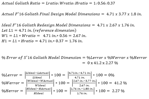
In the calculations shown in Figure 1, when comparing the actual final dimensions versus the ideal final dimensions, we can observe that the actual dimensions did not meet the exact proportions of the real 302 Goliath.
The width of the Goliath is the only measurement that was vastly skewed by a percent error of 41.2%. And as mentioned in the previous paragraph, the main reason for this disproportionality is because the Tamiya tracks and sensors needed to be incorporated into the design. Even though the requirements state that we should have the dimensions proportionate to the ratio, the customer approved the waiver for the implementation of the sensors.
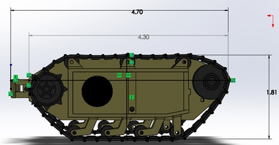
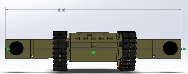
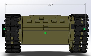
The images shown in Figure 2, 3, and 4 represent the actual measurements of the Goliath model provided by Solidworks. The height is measured from the top wheels to the bottom wheels. I included two measurements of length to show the length with and without the bar attachment. The width also has two measurements, one with the sensor doors opened at max and when the doors are closed.
Final Design
The biggest design change that we incorporated was the hinge movement and sensor doors. After printing the last design for our demonstration, we realized that a snap on hinge was not the best type of hinge for our design because our model is thin and miniature, which made it more likely to break off. Therefore, we determined that substituting the snap on hinges with a rod hinge would provide sturdiness for the hinges on the side parts with side doors, and the top panel with the bottom panel.
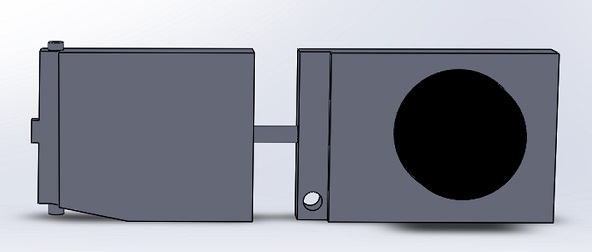
When testing the previous design with the sensors and control algorithm through the obstacle course, we realized that the sensors were detecting the uneven surfaces and ramps. This issue interfered with the autonomous tracking of Biped and resulted in failing the mission objective. To resolve this issue we declared that the sensors must be angled about 15 degrees upward. Also, we realized that we must extend the sensor door to its maximum length of 2.5 inches. This led to the design change of the whole sensor doors and as the design and manufacturing engineer, I decided to split the doors into two parts and incorporate a rod in the center of each part. The rod will allow the piece holding the sensors to move up and down, while the other part will move side to side. The sensor door is shown in Figure 5.
As for the wheels, we increased the thickness of the wheels from 3.5 to 5.4mm and the diameter of the wheels from 6mm to 7.5mm for the bottom wheels and 8mm for the top wheels. The increase will help the Tamiya tracks fit nicely with the wheels intact and will prevent the bumper of the tracks from hitting the wheel holders. Also, the front bottom wheels were redesigned, instead of being angled like the rest of the bottom wheels, we made it come straight down. The reason for this redesign was because the tracks would grind against the angled area which caused more friction and unnecessary noise.
In practice, the PCB was interfering with the 3mm rod for the larger rotating wheels in the front. This resulted in damaging the wires connected to the PCB and the top and bottom parts could not close. Therefore, we had to shift the PCB cut out up by about 1.5mm to relieve any clearance issues and directly solder on jumper wires instead of male header pins.
Originally, we wanted to mount the speaker to the bottom panel but realized that there was not enough room since we changed from an 8ohm 0.25W speaker at 25mm to an 8ohm .5 Watt speaker at 30mm. We decided that the best fit for a speaker mount would be on the top panel. The mount is designed to tightly fit the speaker and includes an opening for the wires of the speaker to be connected to the PCB.
For the bottom, we included screw mounts for the 3Dot board and for the side panel, which was recommended by Jeff Gomes. In the previous design, the connection between the side panel and bottom panel was sturdy enough but still had tendencies to wobble from left to right. So the screw mounts attached to the angled part of the bottom panel will add extra security and less movement between the two parts since there will be more than one plane being screwed on to the side panel. As for the 3dot board, there is a Bluetooth module on the bottom of the board, which causes an uneven surface when being mounted onto the bottom panel. The added screw mounts, which are extruded by 2mm will provide a balanced seat when mounting the 3dot to the bottom part.
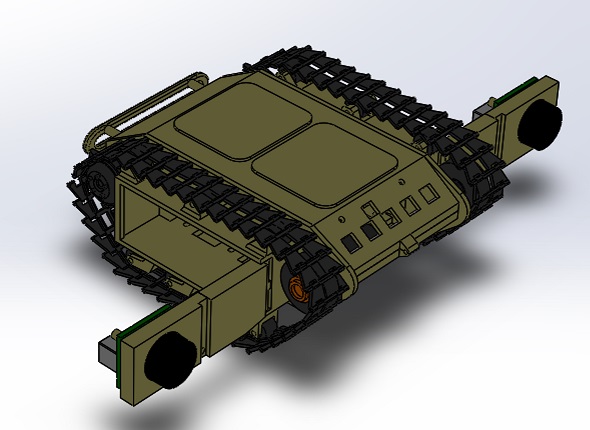
The e final 3D model design in Solidworks, displaying all exterior components including tracks, wheels, sensors, and PCB cut outs is shown in Figure 6.
Conclusion
With the class coming to an end, we have finalized a design that meets the majority of our requirements. We have created a waiver asking to approve the requirement violation of the requirement, where we could not meet the exact appearance of the 302 Goliath because we needed to modify the appearance to include the PCB cut out and the sensors. Overall, the Goliath design was successful, in which we were able to incorporate a functional design for the 3Dot board, PCB, speakers, and motors in a compact size.

