By: Tate McGeary
Summary:
The project’s intent is create a small bipedal robot based off of Dr. Dowdall’s design. The small bipedal robot should then be able to walk around a course, and eventually avoid obstacles. The small bipedal robot will be created with an Arduino based controller, and micro-servos. Due to its size the micro-Biped will be controller by Arxterra RC mode, rather then community mode which is typical of the larger robots.
Object, Mission Profile, and Course
Requirements level 1 and 2:
The object of the project left the group with a series of requirements to fulfill. The primary requirements were reliant on making the microBiPed mobile and functional similar to the BiPed. These requirements were then used to define the microBiPed and the methods of design and type of parts that had to be chosen.
Burn Down and Project Percent Completion:
By: Tate McGeary
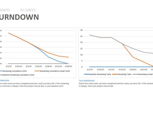
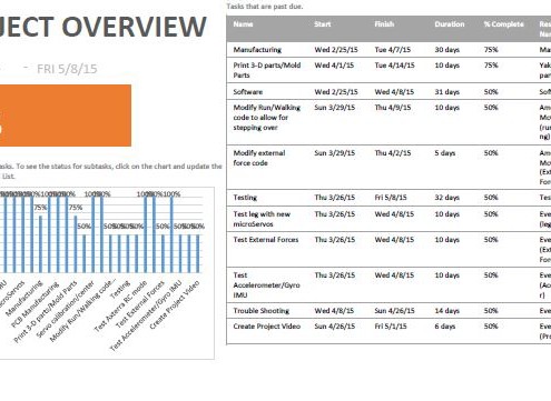
As of the end of the semester, the group has completed 80% of its tasks. Most of the time for the project was spent figuring out how the microBiPed would be controller and the parts used, in addition to the miniaturization of the BiPed frame. The sub 90% completion is present due to a majority of the tasks being marked as 50% if more then 1 task remains. The 75% would be if only 1 task remains in the category. However, even with proper planning one small misstep can and did prevent the group from finishing.
As the burndown shows, with the current standing of the tasks the group did not finish. This however did not prevent the group understanding the areas that needed to be improved upon and figure out how it would be completed.
Detailed Costs:
By: Tate McGeary
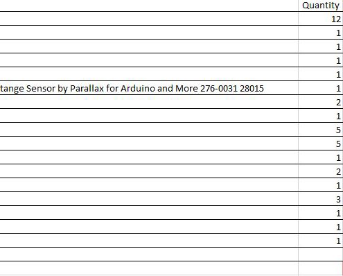
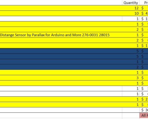
The two pictures below illustrate the predicted cost from the beginning of the semester to the final cost at the end. The primary reasons for reduction of cost was the decision to switch from molding to 3-D printed parts. The rest of the reduction occurred due to parts being either donated or already inventoried during the course of the semester. As one can see the predicted cost was reduced by about $122.
In the final cost picture, yellow are the bought pieces, blue are the removed, and white are components not yet bought. The reason for the remaining white, is usually due to the ability to borrow the components when necessary. This will however present problems if the components are needed and they cannot be accessed.
Schedule:
By Tate McGeary
The schedules below shoe how the tasks were divided between the group members. It is important to note, that allow schedules no matter how flexible cannot be followed through without concessions due to unforeseen circumstances. The method of marking the percent done is 0% means the project has not been touched, 50% means section or category has been started, 75% for a category means only 1 tasks remains, while 100% means the section or category has been completed. Attached is the .mppx file of the schedule.
Design:
By: Yakub Dure
The design the group settle upon, was a smaller version of previous BiPeds. Pictured below was what the microBiPed was intended to look like.
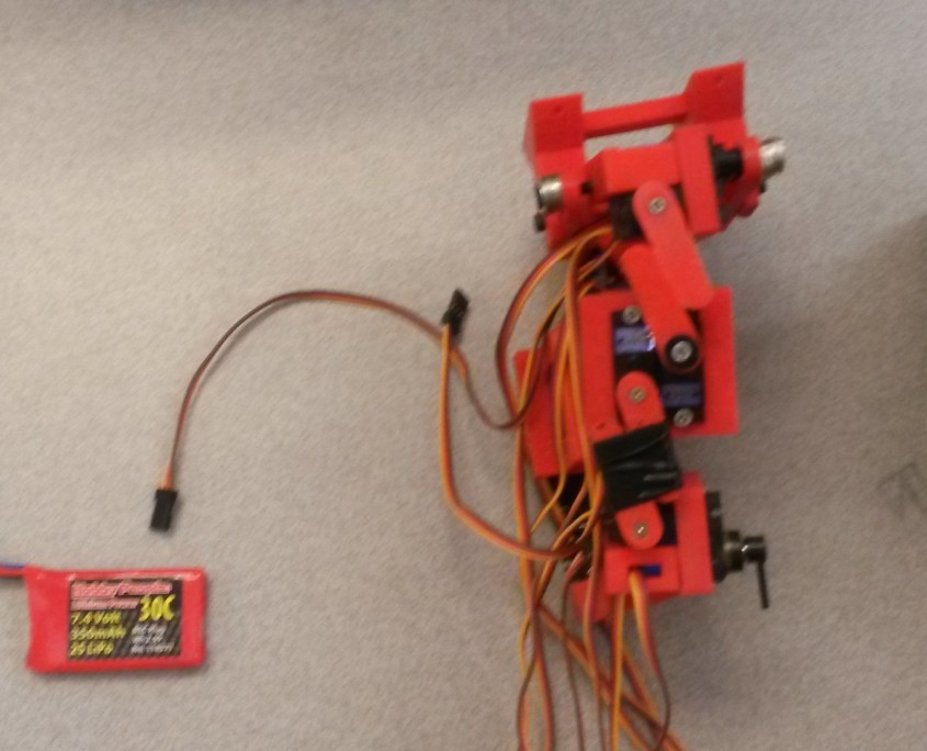
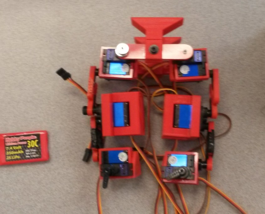
However plenty of issues occurred in the design process. Multiple times the parts were either misprinted, poorly printed, or improperly sized. In the end some of the parts were still incomplete. The skeleton went through a series of iterations so that it could proper fit the micro-servos, MG92B. Other issues that occurred were large feet, the outer thighs of the leg were improperly made for the left leg. This left the group with have to physically modify the parts due to lack of time.
End result is shown below.
The skeleton should be able to house 12 servos, the PCB and batteries. The PCB will be located in the head, the servos act has joints, and the batteries will be housed in the feet.
System Design:
By: Mesfer Aldosari
Despite the reduction in size, change of microprocessor, addition of PWM or shift register, and reduction of code the system block remains somewhat similar to its predecessors. This means that the microBiPed will consist of a Bluetooth compatible device, a microprocessor, PWM driver, power supply and voltage regulators, all working in conjunction together. For further explanation click here.
Interface Definitions:
By: Ameen Alattas
In a previous blog, the group detailed out the pin connections . The blog shows through a chart how the pins connect and what ports will be taken by each component. The chart will also contain the pins and their function for each component. Some components had to modified via software, due to incompatibility with the Arduino Micro.
Resource Reports
Mass Report
By: Mesfer Aldosari
The group had to maintain a mass below 1 kilogram due to the constraints of the micro-servo. The group decided upon the weight of 1 kilogram because during the calculations the group found the strength the servo rapidly deteriorates as the armature lengthens.
Power Report
By: Ameen Alattas
The group had to determine the power consumption of the components in order to determine the size of the battery. If the components chosen for the micro-BiPed consume too much power, then the group may not be able to find a battery small enough, and light enough to complete the project.
Tasks
Micro-controller
By: Tate McGeary
When reviewing the code, the group found out that footprint left behind by the code was 14kb FLASH and 4.7 kb SRAM. Since the group was no longer using the Arduino ADK, concern grew on how to compensate because most other small Arduino devices do not have enough SRAM. After research, the group found the Crumbuino Mega. The Crumbuino Mega is an Atmega 2560 miniaturized micro-controller that would fulfill all the needs of the group. However, some issues occurred which are listed in this blog.
Reduction of memory
By: Tate McGeary
Due to unforeseen issues with the Crumbuino Mega, the group decided to use a smaller Arduino device. The Arduino Micro was chosen due to it small footprint and larger SRAM compared to the Atmega 328 chips. The Arduino Micro uses an Atmega32u4, which has 2.5kb SRAM and 28kb of FLASH, which means that the BiPed code is still too cumbersome. To compensate the group reduced the code by taking out the calibration function of the code. How this was done, is explained in this blog.
Speed Calculation and Course Time
By: Ameen Alattas
In order to know the baseline on how to size the battery, the group needs to calculate the possible speed of the microBiPed. This is explained in the following blog.
HC06, HC-SR04, MPU-6050
By: Ameen Alattas
The microBiPed uses Bluetooth to communicate with Arxterra, the HC-SR04 to avoid obstacles, and the MPU-6050 to maintain stability. The goal in this series of blogs was to test the functionality and if the components could be implemented into the microBiPed. The tests are explained here.
MicroBiPed Telemetry Interpretation
By: Tate McGeary
After the testing of the HC-06 confirmed the functionality of the component, the group then went on to implement a decision tree for the movement of the BiPed. The process is explained here and the implementation using LEDS to represent direction is shown here.
3-D Printing versus Molding
By: Yakub Dure
The goal is to determine the best method for the microBiPed in the production of parts. The group decided upon 3-D due to cost and a few other reasons explained here.
Material Choice
By: Yakub Dure
In addition to choosing method of production, the group had to decided upon the material to use. Since the research was done in conjunction to determining the process standard molded plastics are apart of the study. However, the group ended up going with PLA due to its lightweight and easy to produce qualities. The blog is here.
Expanding PWM pins of Arduino Micro
By: Ameen Alattas
The other issue that came about due to the Arduino was the lack of PWM pins. The Micro has 7 PWM pins, however the group needs 12 PWM pins to control 12 servos. To do this the group decided upon the TLC5940. THe blog on the basic set-up is here.
TLC5940 and the Arduino Micro
By: Tate McGeary
Using the TLC5940 is relatively easy when using an UNO, or Mega variant as the libraries are set up for those devices. Since the Arduino Micro uses neither the ATmega 328 or 2560, the group had to figure out what modifications to the library needed to be done. The explanation on the modifications can be found here.
Servo Test Physical
By: Ameen Alattas
It is important to know the actual values of current that the servos consume because they can differ from the theoretical. This will allow the group to create the power budget to be used in the sizing of the battery. It will also help give an idea of torque values servos. The blog is found here.
Servo Torque Calculations
By: Mesfer Aldosari
In addition to a physical test, the group also performed a theoretical. The theoretical will allow the group to check the torque at many lengths of armatures without having to go through and actually test the length, and weight. The blog for this is found here.
Battery and Regulators
By: Mesfer Aldosari
Based off of the power budget, and speed calculations the group knows that the microBiPed needs to run for at least 7 minutes and deliver in worst case 2A, the group can size the battery appropriately. The group will also have to use regulators to limit the total output current and drop the voltage since most batteries are 7.4 volts. This blog for this post is here.
PCB board design, received, issues, and corrections
By: Tate McGeary
The PCB board was ordered and designed based off of the interface definition. Once received a continuity test was done on all the ports, the PCB was done correctly. However, when reviewing the circuit to install the components it was determined that the original interface definition is wrong. This means that a series of problems rose, to see issues and how they may of been resolved see here.
MPU-6050
By: Tate McGeary
To stabilize the group had to a MPU-6050. After Ameen confirmed the proper wiring and that the device is in working order, the group then implemented the gyro in controlling a servo through the Arduino Micro and the TLC5940. For an explanation go here.
Project Documentation
- PDR: µBiPed_PDR
- CDR: µBiPedProject – CDR_compiled
- Arduino Code
- CAD Files: Please e-mail about CAD files as they are not EAGLECAD.
- SolidWorks Files
- Calibration using Processing: HERE


