Final Pathfinder Design
Author: Adolfo Jimenez (Manufacturing Engineer)
Verified By: Jordan Smallwood (Project Manager)
Approved By: Miguel Garcia (Quality Assurance)
Table of Contents
Introduction:
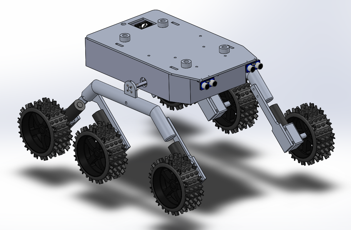
Figure 1: Isometric View of the Pathfinder Robot
Many modifications were made to our original designs of the pathfinder rover. These designs were implemented to accommodate the requirements of the rover being able to operate in a dessert environment. Our preliminary design involved the use of an electronics box, similar to the one used by previous semesters to house all the electrical components required for the operation of the robot. The use of the box, combined with the considerable real estate taken up by both the battery and differential gear mechanism, required a redesign of the housing for all of our components.
Aluminum Body:
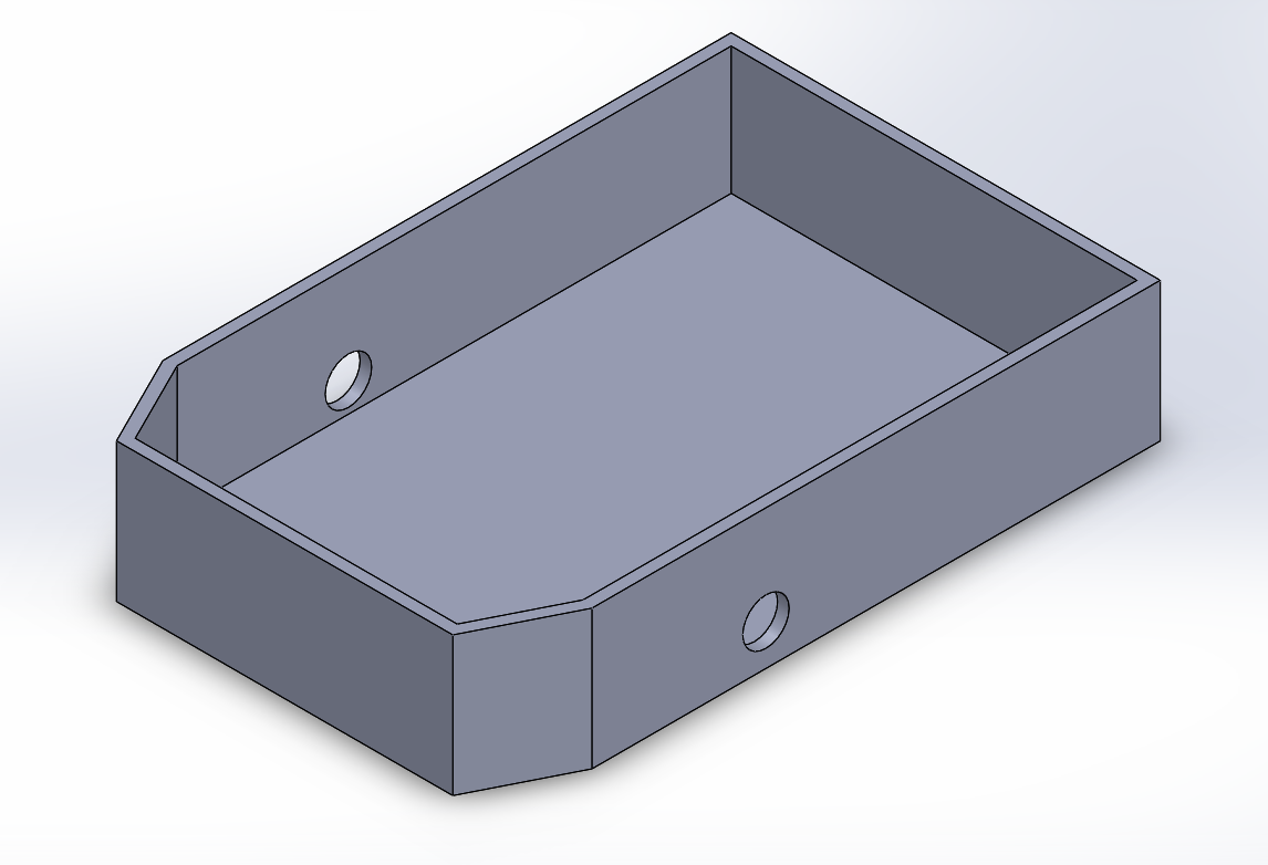
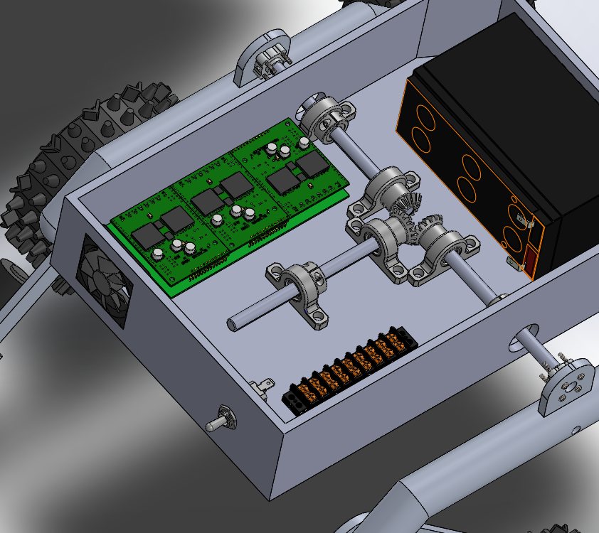
Figure 2: Isometric view of Rover body without top cover
The main design update was the use of an entire aluminum body with dimensions 3” x 14.25” x 9.25” constructed from ¼” thick aluminum alloy 6061 that would be used to house not only the electrical components but the differential and battery as well. This new aluminum housing required us to change the orientation of our differential from previously being mounted underneath the aluminum plate to above the base of the new aluminum body.
Mounting Hub:
Figure 3: Rocker-Bogie with Differential Gear System Re-oriented
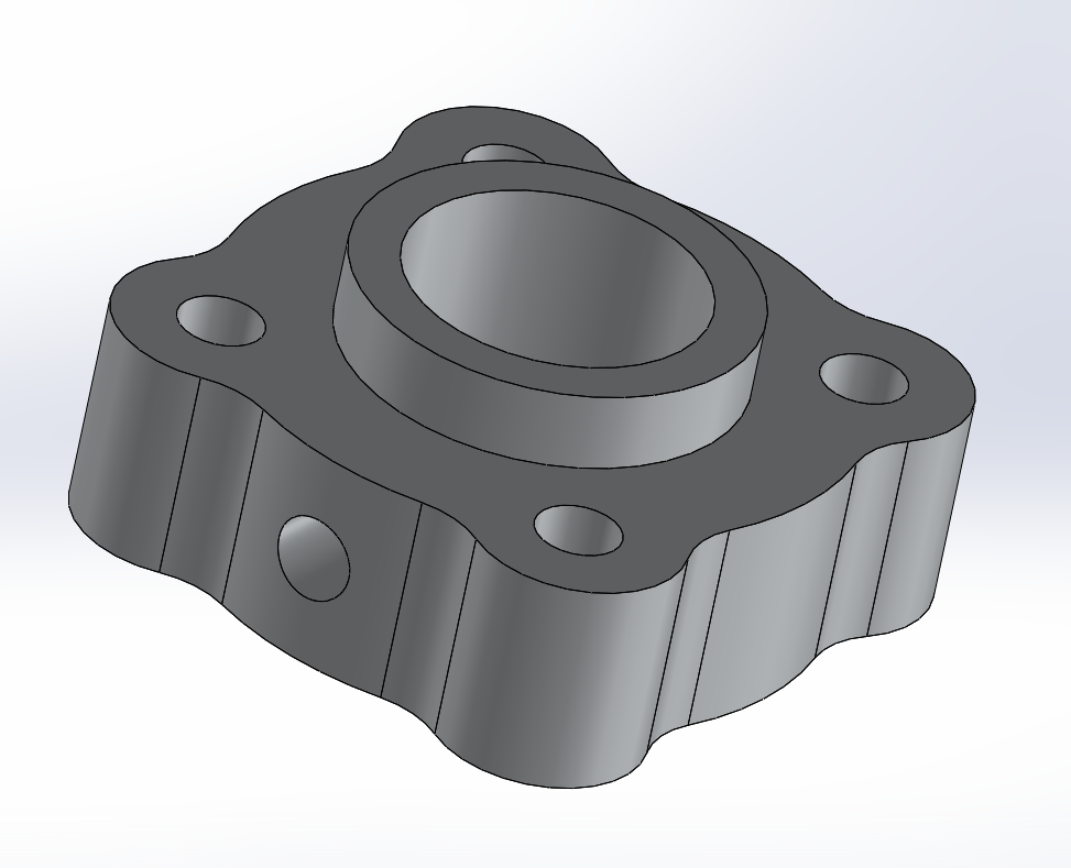
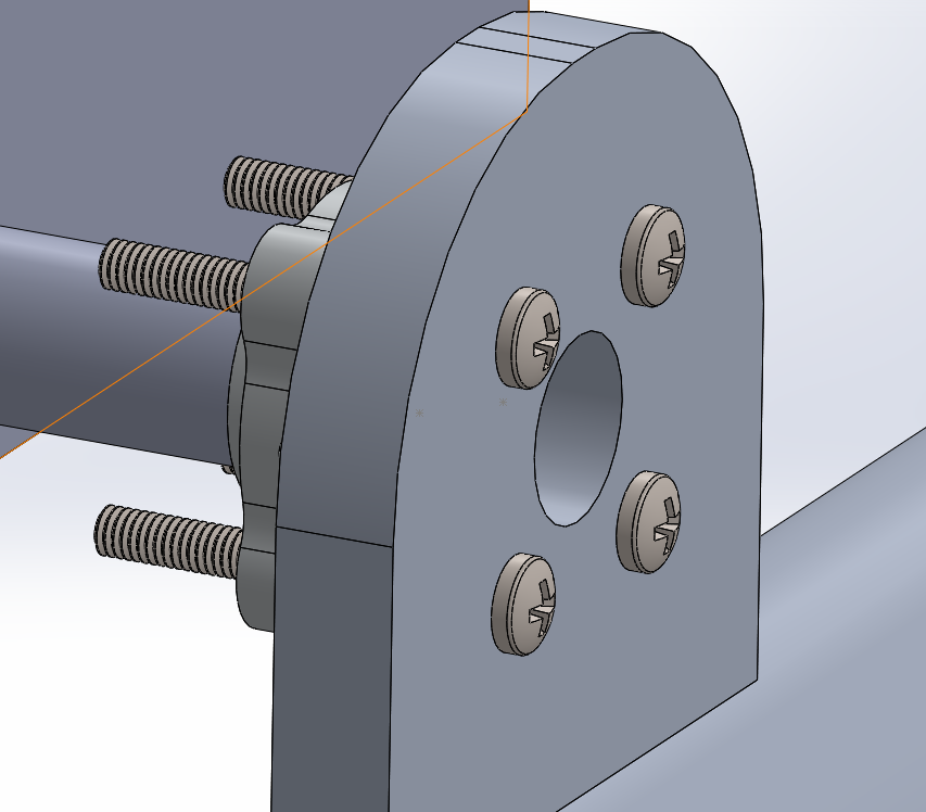
Our requirement to make the rover able to be disassembled forced us to find a solution other than welding to fix the differential axels to the wheel assemblies. The differential was mounted to the side arm assemblies (making up the rocker-bogie suspension system) using a 3/8” set screw hub purchased from SparkFun.
Figure 4: Set screw Hub (top); Screw Hub mounted to wheel assembly (bottom)
New Motors:
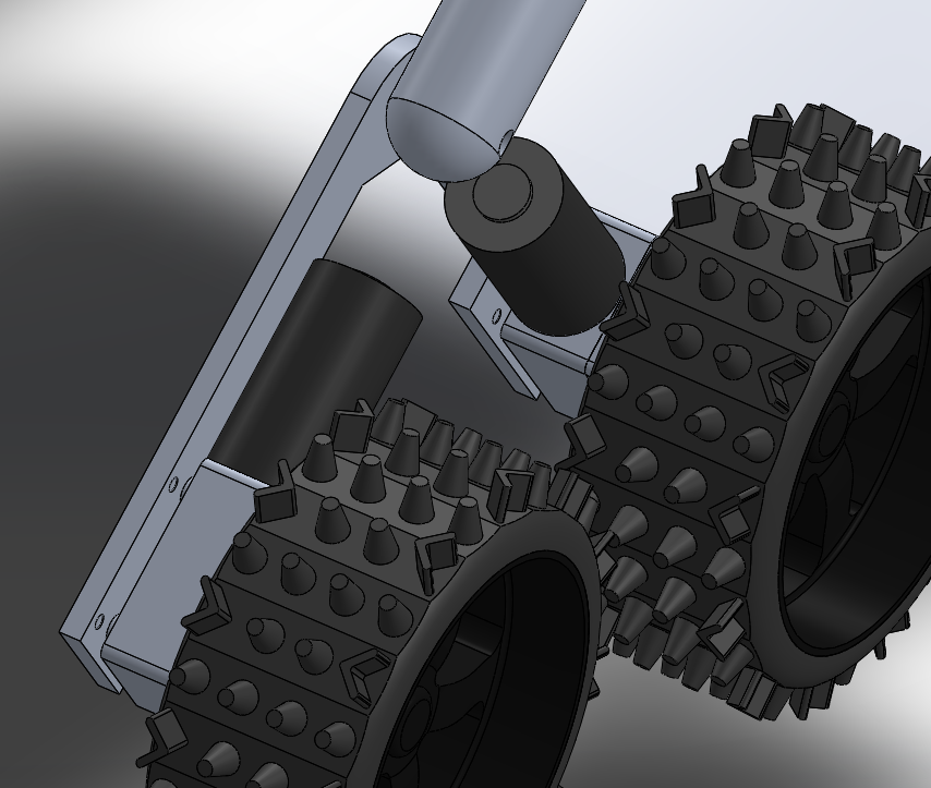
Our need to have encoders to be able to measure and vary the speed of our wheels to implement the slip differential required us to purchase new motors with included encoders. These new motors were slightly smaller than the ones used by previous semesters, required less current to operate and generated more torque. The only trade-off being that these new motors operated at a much slower RPM. Though the new motors themselves were different in size to that of the previous motors, fortunately for us, the gearbox on the new motors were the exact same size as the ones found on the old motors, allowing us to easily mount our new motors on the same motor mount used of the rover. In addition to the new motors, new thrust bearings were purchased to replace the previous radial bearings that were incorrectly acting as spacers on the bogie mechanism.
Figure 5: View of Rover Bogie with upgraded motors.
Internals:
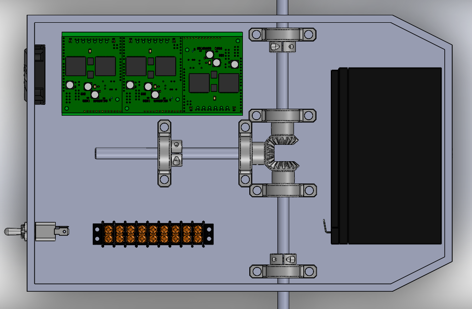
Figure 6: Isometric and top-side views of robot internals
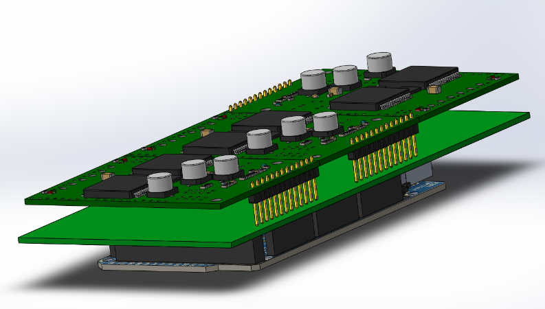
Inside the rover body can be found all the electrical components and wiring for the rover. Located at the very front of the robot is the 12-Volt rechargeable battery used to power the entire rover. At the very center is the differential mechanism requiring most of the real estate within the rover body. On the right side of the differential is the power distribution block, it is used to redistribute the power from the battery to the external motors as well as the rest of the internal electronics. On the left side of the differential can be found the custom PCB for our robot, connecting our 3 sets of paired motor drivers to an Arduino Mega.
Figure 7: Custom PCB connecting motor drivers to Arduino Mega
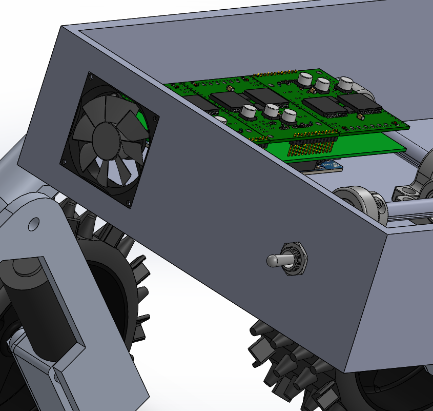
The heat generated by the motor drivers and the rest of the components was cooled down using a fan located to the rear of the rover, near the custom PCB. The need to keep eternal particles out of the rover had us opt for a fan with included filter. To the right of the fan, also on the rear, is a toggle switch which can be used to turn the robot on and off.
Figure 8: Rear view of rover showing fan and toggle switch
Sensors/Lid:
Figure 9: Top cover with Ultra-Sonic sensors
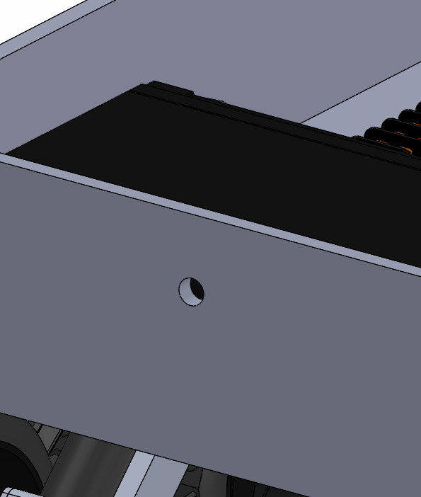
The aluminum panel making up most of the rover chassis for previous generations was repurposed to serve as a top cover. To do this, the triangular side assemblies that were once used to connect to the rocker-bogie suspension system were removed. The sensors and sensor mounting plates, however, were left intact. With all electrical components located inside a closed body, a method of getting the wiring to the outside sensors and LED’s required, to combat this, a small hole was drilled at the front of the rover body just wide enough to allow wiring through.
Figure 10: Hole at front of rover for sensor wiring
Conclusion:
The incasing of our components in an aluminum body ensures that our electrical components, as well as our differential system, will be more secure from the elements. The obvious danger in using a conductive material to enclose electrical components means add precaution when wiring everything up. Much to our dismay, accidental contact between the wiring and the rover body can lead to short circuits, in our case that meant the frying of some of our components. For future semesters, we recommend extreme caution when wiring components inside the rover. A small layer of non-conductive material such as rubber could be used to combat this and help prevent accidental short-circuiting. Rubber could also be used to somehow cover holes such as those made for the differential axels and ultrasonic sensors to further prevent external particles from entering the robot. The reason for this being that large enough accumulation of particles between the differential might cause it to jam, or worse, conductive particles such as iron could also get into the components and cause short-circuiting.
References:
- Solidworks Files: https://drive.google.com/drive/folders/11zZJXZYqD2LwFxzG09dudBXihLIsBzNR
- Fall 2016 Semester design: https://www.arxterra.com/the-pathfinder-fall-2016/
- Custom PCB: https://www.arxterra.com/custom-chassis-pcb/
- Updated Bearings: https://www.arxterra.com/bear-ings/

