Fine Tuning the Printer
By Omair Tariq, Systems and Test Engineer
Scope
There are two issues to ensure correct flow of the mixture: Volume and Temperature Control of extrusion apparatus. The extrusion apparatus consists of a syringe and a needle attached to the base of the syringe. Temperature control was addressed by attaching a heater to the body of the syringe. However, the gel was still solidifying at the base of the syringe and at the needle. This issue was addressed by attaching high-wattage resistors to the base and the needle. The details concerning the correct temperature control are addressed in a separate blog post. The purpose of this test is to determine the ideal needle diameter and Slic3r settings for the 3-D BioPrinter once the problem of temperature control has been addressed.
Equipment Needed
|
Equipment |
Quantity |
|
3-D BioPrinter |
1 |
|
Vernier Caliper |
1 |
|
Agarose Solutions of varying percentages |
50 ml |
|
Needles with different gauge diameter |
1 |
|
Laptop with Slic3r and Pronterface Installed |
1 |
|
USB Cables |
2 |
Table 1. Equipment needed for accuracy testing
Procedure
For the following test prints, a solid 20mm x 20mm x 5 mm cube was printed
- It was decided to start with a 1% agarose solution and a 18 gauge syringe needle[1]. This led to an overflow of the liquid from the syringe as illustrated in Figure 1. Due to this overflow, the liquid did not have enough time to solidify. Therefore, the print was stopped even before the first layer was completely printed. The Slic3r settings shown in Table 2 were used for this test print.
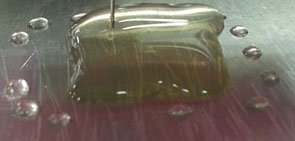
Figure 1 Overflowing liquid
|
Perimeter |
Value |
|
Nozzle diameter (18 gauge needle inner diameter) |
0.8mm |
|
Filament Diameter |
40 mm |
|
Travel Speed |
50 mm/s |
|
First Layer Speed |
20 mm/s |
|
Fill Density |
1 |
|
Fill Pattern |
Concentric |
|
Top/Bottom fill pattern |
Concentric |
Table 2. Slic3r settings used for 1st test print
- It was then decided to switch to a needle with a smaller inner diameter: a 20 gauge needle was chosen. Subsequently, the nozzle diameter and the filament diameter had to be changed in Slic3r. The new Slic3r settings are shown in Table 3. This yielded a much better result as can be seen in Figure 2. The flow was slow enough to facilitate the gelling of the liquid. Even after gelling, the gel structure was not as strong as expected in that it was not able to hold its weight which was a level 1 requirement. Therefore, It was decided to use 2% agarose gel which would be stronger than 1 % agarose gel after gelling. 2% agarose gel has the same gelling temperature as 1 % agarose gel. Therefore, there was no need to adjust the temperature of the syringe. It was also decided to use 4% starch in the solution to increase the viscosity of the fluid. This slowed down the flow of the liquid through the needle without the need to change temperature. Starch and Agarose are both carbohydrates, therefore adding starch did not alter the viability or biological nature of the solution.
|
Perimeter |
Value |
|
Nozzle diameter (20 gauge needle inner diameter) |
0.6 mm |
|
Filament Diameter |
29 mm |
|
Travel Speed |
50 mm/s |
|
First Layer Speed |
20 mm/s |
|
Fill Density |
1 |
|
Fill Pattern |
Concentric |
|
Top/Bottom fill pattern |
Concentric |
Table 3. Slic3r settings used for 2nd test print (Changes highlighted)
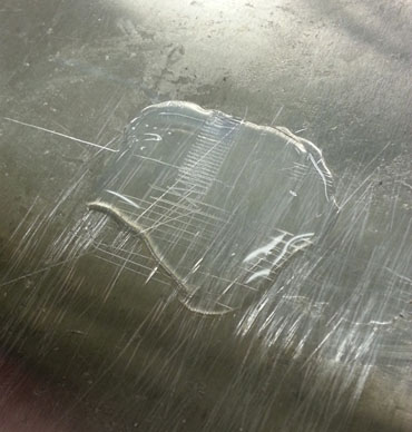
Figure 2. Overflowing gel
- A test print was then carried out using a 2 % agarose, 4 % starch solution (See Table 4 for exact composition of solution).
The resulting solution had just the right amount of viscosity, which justified the use of starch. The final structure was also strong enough to hold its own weight, which justified increasing the concentration of agarose gel. This structure also had the correct dimensions. But there was one problem; instead of being a solid cube like ‘American Cheese’, the block turned out like ‘Swiss Cheese’ with air bubbles in the middle.
|
Chemical |
Quantity |
|
Water |
50 ml |
|
Agarose |
1 g |
|
Starch |
2 g |
Table 4. Chemical Composition of 2% Agarose 4 % Starch Solution
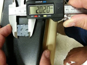
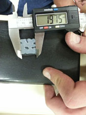
Figure 3. Test Print using 2% agarose and 4% Starch
- During the third test print, it was observed that the travel speed of the extruder increased after printing the first layer. This was problematic since it was not possible to adjust the flow of the liquid for two different travel speeds. Even though the first layer turned out fine, the extruding liquid broke off contact with the structure at certain points in the 2nd layer due to a faster speed. This break in contact in the second layer meant that there was also break in contact in the third and subsequent layers leading to a domino effect. . We then switched to advance mode in slic3r that gave us a better control of the various speeds of the printer. All these were set to a smaller and equal value of 20 mm/ s. The settings are shown in Table 5. The structure printed using these settings are shown in Figure 4.
|
Perimeter |
Value |
|
Nozzle diameter (20 gauge needle inner diameter) |
0.6mm |
|
Filament Diameter |
29mm |
|
Travel Speed |
20 mm/s |
|
First Layer Speed |
20 mm/s |
|
Fill Density |
1 |
|
Fill Pattern |
Concentric |
|
Top/Bottom fill pattern |
Concentric |
|
Perimeter Speed |
20 mm/s |
|
Small perimeters |
20 mm/s |
|
External Perimeters |
20 mm/s |
|
Infill |
20 mm/s |
|
Solid Infill |
20 mm/s |
|
Top solid infill |
20 mm/s |
|
Support Material |
20 mm/s |
|
Bridges |
20 mm/s |
|
Gap Fill |
20 mm/s |
|
All Acceleration Controls |
0 mm/s2 |
Table 5. Slic3r settings used for 4th test print (Changes from previous step highlighted)
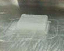
Figure 4 Final Printed Structure
The actual dimensions of this structure were also very close to the expected dimensions.
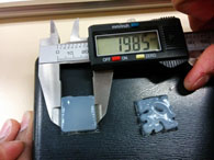
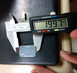
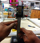
Figure 5. Measurements of Final Printed Structure
Conclusion
A 2% Agarose and 4% starch solution is the ideal solution to be used in the bioprinter. The settings used in Step 4 of this test plan are the ideal settings for the bioprinter when it is being used to print 2% Agarose and 4% Starch solution.
[1] – For needle diameters, check: http://en.wikipedia.org/wiki/Needle_gauge_comparison_chart