Fritzing: A How to Guide
Fritzing is an open-source hardware initiative that makes electronics accessible as a creative material for anyone. We offer a software tool, a community website and services in the spirit of Processing and Arduino, fostering a creative ecosystem that allows users to document their prototypes, share them with others, teach electronics in a classroom, and layout and manufacture professional pcbs.
You can find and download Fritzing software at the link below.
First, select the type of breadboard that suits your needs in the Inspector window. For Simple Robot the “full+” is desired, but for smaller projects the “half” or “half+” could suffice.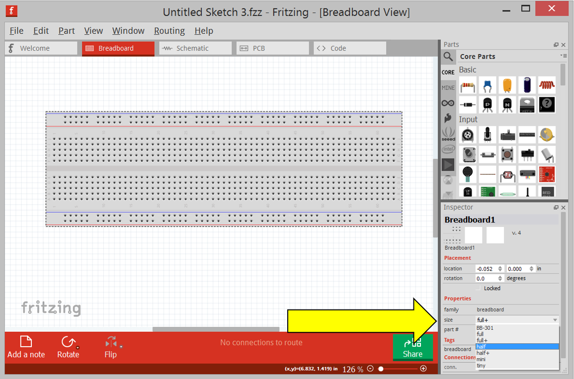
For an Arduino Microcontroller (MCU) navigate to the Parts window and click the Arduino logo: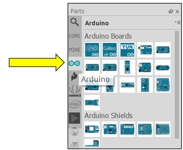
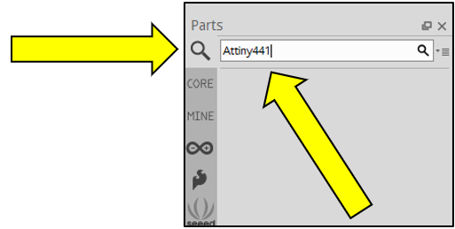
However, for this Simple Robot, the ATtiny441, by Atmel will be used (Spark Fun Pro Micro recommended for 3Dot stand-in). Let us see if the parts library has this MCU using the search field in the Parts window:
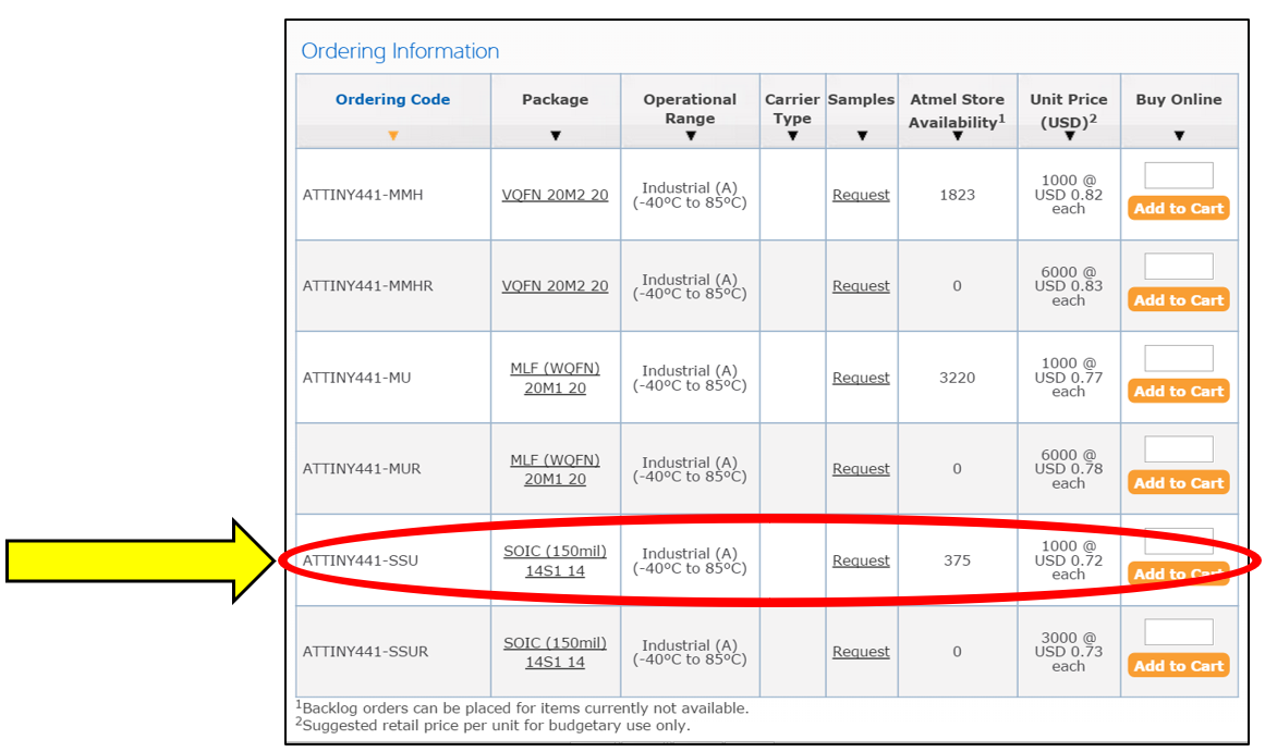
The search did not yield any results… However, ATtiny441 comes in several packages, the one that Simple Robot will be using is the Small Outline Integrated Circuit (SOIC).
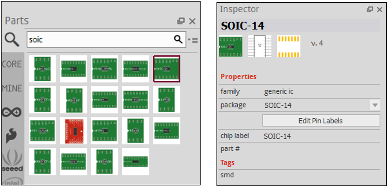
Luckily Fritzing has generic devices in the parts library that can be used to emulate the device you want. Type “SOIC” in the search field:
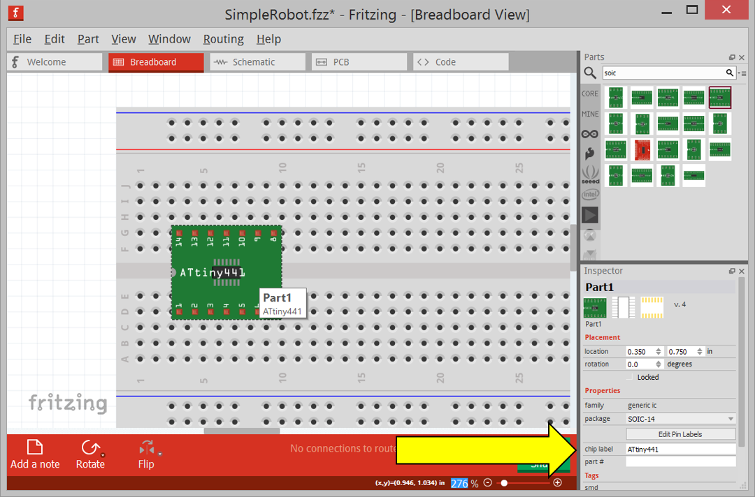
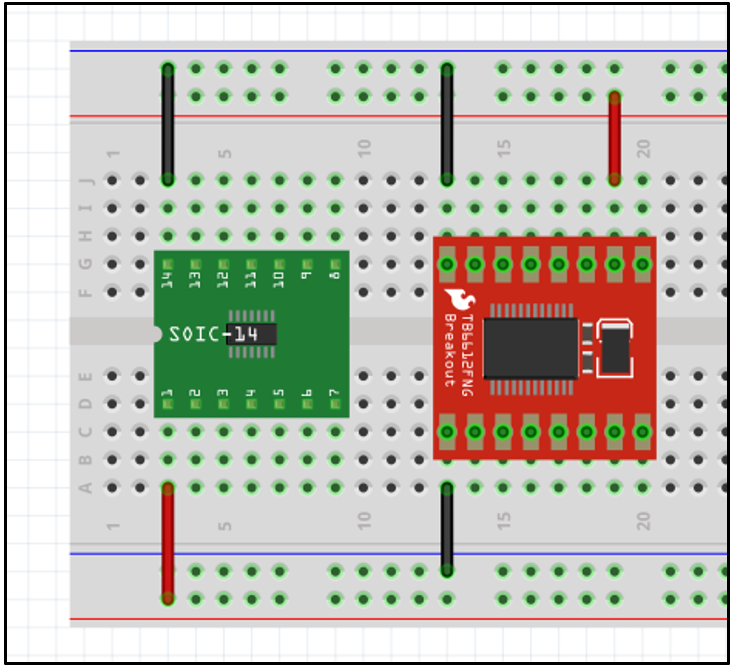
Once the part is placed, it can be renamed to help identify it in the Fritzing diagram. Double click the part on the board, and type the new name in the field “chip label” in the Inspector window.
Connect Pin1 to the positive rail on the bus bar, and Pin14 to the ground rail. This is done by clicking on one hole and dragging the mouse to the destination hole: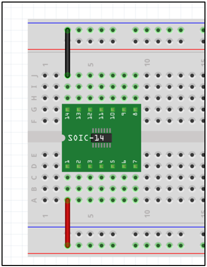
The color of the wire can be changed by right clicking the wire and selecting Wire Color>(name of color).
Next, let us set-up the motor driver. Simple Robot will be using the SparkFun Motor Driver – Dual TB6612FNG. By typing “TB6612FNG” into the search field in the Parts window, the driver comes up. Drop this onto the workspace, right click the device and select Rotate>Rotate 90° clockwise. Refer to the product webpage for the pin connections for Vcc and GND: https://www.sparkfun.com/products/9457.
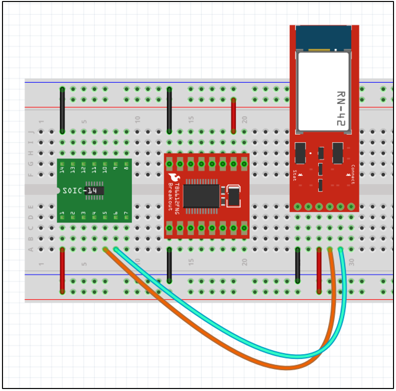
Next, referring to the Resource Worksheet, a Bluetooth module needs to be instantiated. The Bluetooth module desired for Simple Robot does not exist in the parts library, however there is a similar module with the same pin connections. The Bluetooth Mate Silver will be used for this Fritzing.
The Bluetooth module TXO pin needs to be connected to pin 5 on the ATtiny441, and the RXI pin to pin 6. This information is available on the Simple Robot Resource Worksheet.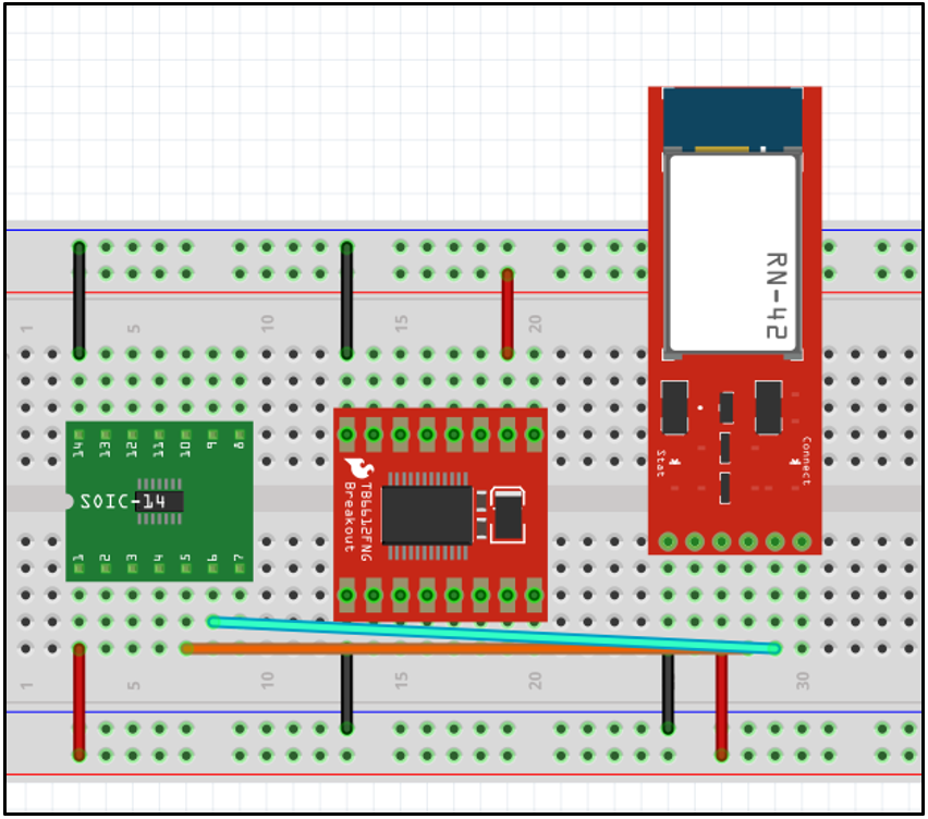
This looks like a mess with the wires crossing, and it is hard to tell where the orange wire from pin 5 on the ATtiny441 is connected to. This can be fixed by bending the wire: hold down Ctrl, click and hold the middle of the wire, and drag to desired curvature.
Curvy wires make the breadboard look realistic
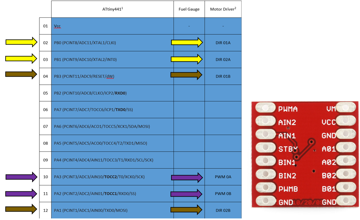
Next, let us connect the ATtiny441 to the motor driver:
The Resource Worksheet (left) and pin labels for the motor driver (right)
PWM signals in purple, “A” directions in yellow, and “B” directions in brown
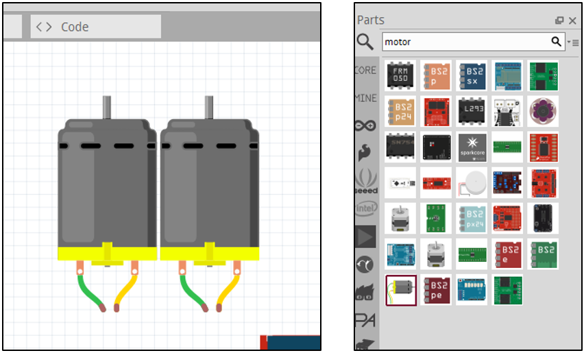
Next, let us connect the motors to the motor driver. These are denoted as A01, A02, B01 and B02 on the motor driver. Search the parts library and just use the generic motors:
Pro tip: start the wire from the motor terminals to automatically match the wire lead colors
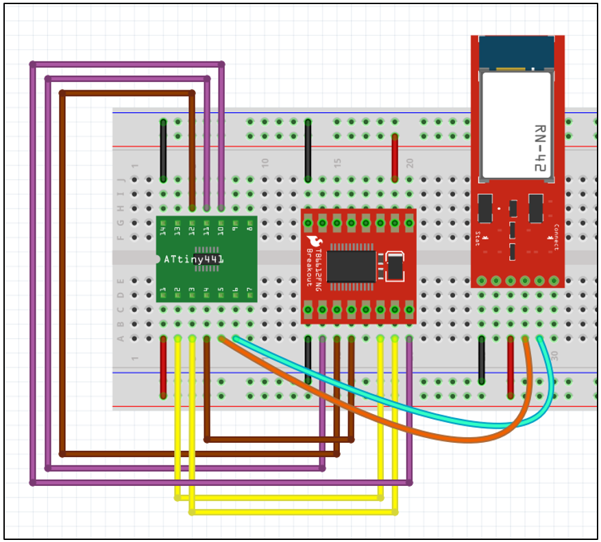
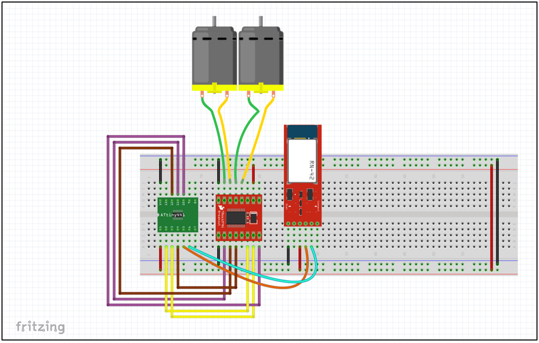
Your final Fritzing should look like this:

