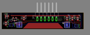
Generic Color Sensor Hedge follower PCB Layout
Written by Charles Banuelos
The PCB design below is for a generic hedge following shield. The PCB is a work in progress with the finalizing of the dimension dependent upon the testing of the color sensors. The LEDs chosen are significantly larger than the previous design and this is due to availability.
Update 11/30/2017
The PCB design was finalized and sent to OSH Park to be fabricated. The color sensors are placed 5.48 mm away from the edge of the board. The LEDs are placed 5.64 mm horizontally away from the color sensor towards the center of the board. The LEDs were changed due to availability as well as the issues with size. The orginal LED was too large and suitable replacement with similar specs was found. The final board dimensions are 10.87 mm wide by 55 mm long. The color sensors are placed 40.41 mm apart. The final draft of the PCB has the caster wheel cut out for 3DoT chassis as well. The boards were received on 11/21/2017 and are currently being assembled.
Update 12/12/2017
This design was able to work for only one of the color sensors on one of the boards. The other color sensor was intermittent. This lead me to believe that the problem is in the soldering. The fabrication portion of this designed was plagued with many problems. The color sensor pads themselves are extremely small so when placed on the solder paste by hand the sensor would move and create bridges. The only way to mitigate this is to use the pick and place machine to ensure proper placement. The another issue found was that when a board was trying to be fixed with a heat gun the parts would burn before the solder would melt. This to could also be fixed by using the pick and place to ensure proper placement the first time. The last issue was with the stencil. The stencil would get clogged on the color sensor holes due to that fact they were very small. The only option to mitigate this is clean the stencil thoroughly after each use as well as use flux to ensure solder is in the right place.


