Electronics and Control Resources
Electronics and Control Resources Overview
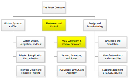
MCU Subsystem and Control Firmware
Task Summary:
- Software Definition
- MCU Communication Firmware
- MCU Subsystem Command and Telemetry Firmware
- MCU Subsystem Control Firmware
Write software subroutines and functions as defined by the software system block diagram. For robots implementing complex motion algorithms, this includes creating a data structure array in SRAM or Flash program memory to define the motion. Specifically, responsibility of the electronics and control engineer will be to write the firmware required to translate commands into control signals to the actuators, read sensors and translate into data bytes, and implementation of any control algorithms. Communication with the Bluetooth module and decoding of command packets is the responsibility of the systems engineer. The systems engineer is also responsible for collecting and packetizing the data bytes and subsequently sending them to the Bluetooth module.
Qualifications
A background with embedded systems, the Arduino IDE, and the C++ programming language or a desire to learn is a plus.
Software Definition
Develop a software system block diagram. The description of the block diagram should define the function of each module and how they will communicate. For example, the number of arguments and their data type, plus return value and data type.
MCU Communication and Telemetry Firmware
The Micro-Controller Unit (MCU) Communication firmware receives and decodes commands and sends telemetry to the Bluetooth device on the robot. The software’s responsibility stops once a command is decoded. For most projects, the E&C engineer will adapt existing C++ programs written within the Arduino IDE for this purpose. If the project does not fall within the category of having an off-the-shelf application to decode commands and send telemetry, then it would be necessary to have a strong background in programming in C++.
E&C – MCU Subsystem Command Programming
To control actuators and read sensors, the software will interface with the peripheral subsystems of the microcontroller including: Timers (e.g., Fast PWM mode), ADC, TWI, SPI, EEPROM, and USART. The Robot Company has developed extensive material on working with the ATmega328P and on how to program its subsystem modules in C++.
MCU Subsystem Control Firmware
The successful candidate(s) will be responsible for the onboard software associated with the stability and tracking control of the robot. Most robots will implement one or more PID control algorithms.
Control input will typically be from an IMU. For this sub-task a background in embedded systems, C++ programming, and control theory (EE470 and EE471) or a desire to learn is a plus.
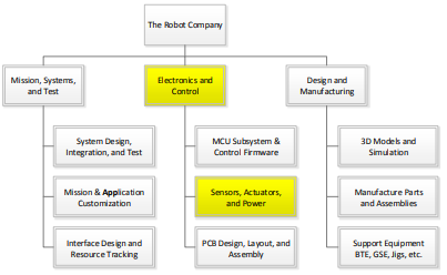
Sensors, Actuators, and Power
Task Summary:
- Define sensor suite
- Define actuators including electromechanical devices and subsystems
- Define communications subsystem
- Define power subsystem
Electronics and control engineer is responsible for selecting and implementing the sensors, actuators and power subsystem to be carried on the robot.
Sensors
Sensors can be as simple as a resistor divider to measure battery voltage and as complex as a SLAM mobile device. In the following paragraphs, sensors typically found on a robot will be discussed.
For measuring target distance, a number of sensors need to be considered including IR, Lidar, Ultrasonic, or camera. Trade-off studies to select a sensor should consider how measurement errors are introduced by the environment (e.g. lighting, reflections, and target surface properties). Also, consider the peripheral subsystem required by each sensor type. These may include the ADC or a serial peripheral interface like the I2C, SPI, 1-wire, and USART. A wealth of information can be found on the Internet and below.
For measuring the distance traveled by a robot, consider the addition of a shaft encoder. The trade-off study should investigate traditional (op to and hall effect sensors) and sensorless (commentator and back emf) solutions for measuring the rpm’s of a DC motor.
For measuring angular rotation and/or velocity to control the stability and tracking of the robot, consider gyro, accelerometer, and magnetometer or some combination of all three incorporated into an Inertial Measurement Unit (IMU). If an IMU is adopted, sensor data may be smoothed using a Complementary or Kalman Filter algorithm. Some commercially available modules incorporate both the IMU and filter.
Actuators
An actuator is defined as any output device. This includes optical devices like LEDs and Lasers. It also includes electromechanical devices like solenoids, servos, and motors.
Electromechanical Devices
Specification of electromechanical devices, like servos and motors, should be based on quantitative system/subsystem design requirements. From these “specifications”, a trade-off study is typically conducted. The trade-off study usually takes the form of a table where the robot’s desired specification for the electrometrical part is in the first column. The subsequent columns contain the specifications gleaned from the datasheet of candidate commercial off-the-shelf (COTS) parts. The selected parts are then purchased and tested against the original robot specification. These tests should consider static and dynamic loads plus life-cycle testing under worst-case load conditions.
Case Study
Up to the Spring 2016 Semester, no SpiderBot has ever completed its mission due to insufficient static and dynamic modeling (back of the envelope and at 3D modeling) at the system level, mass resource management, and life-cycle testing under load conditions.
Electromechanical Subsystems
Electromechanical devices are often combined into subsystems. Robots’ subsystems may include the powertrain and a pan and tilt platform.
Powertrain
The powertrain includes: DC motors and/or servos, transmission (the “gearbox”), and drive electronics (H-Bridge, Shift Register, Power Transistors …). For this subsystem, an educational background in motors and motor control (EE451) or a desire to learn is a plus.
Pan and Tilt Platform
For the robots, the pan and tilt platform carry the mobile device (Android or iPhone). Actuators may include a stepper motor or servo for panning and almost always a servo for tilting.
Communications
For most robots, a Bluetooth module will be incorporated into the design. With Bluetooth comes the ability to integrate with the Arxterra control software suite.
Power
The power subsystem may include batteries, charging circuits, DC-to-DC converters, and voltage regulators (linear and LDO). For some robots, consider the addition of solar panels.
DC-to-DC converters may step-down (buck) the input voltage, step-up (boost) the input voltage, and in some cases both. A step-down (buck) converter is also referred to as a UBEC which stands for “Universal Battery Eliminator Circuit”.
Research battery solutions based on quantitative subsystem requirements, resource reports (mass and power), and project requirements (mission duration, safety, etc.). Battery technologies include, but are not limited to, NiCD, Nimh , LiFePO4, and Li-Ion/Polymer. Based on requirements, other power sources may be investigated such as solar.
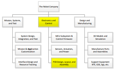
PCB Design
Task Summary:
- Working from interface matrix, create a Fritzing diagram
- From fritzing diagram, build breadboard
- Write C++ test software programs both to control the actuators and collect data from the sensors
- Test breadboard
- Using Eagle CAD (schematic capture), create electrical schematic
- Test finished PCB
Working from the PBS, System Block Diagram, and Interface Matrix, provided by the system engineer, the electronics and control engineer designs the robot’s Printed Circuit Board (PCB). Working from the provided material, the electronics and control engineer also creates a Fritzing diagram, makes and tests the breadboard, and captures the design, in the form of a schematic, using CAD software (typically Eagle CAD). The manufacturing division is then responsible for laying out the PCB and providing to the Electronics engineer a completely assembled PCB. The electronics and control engineer is then responsible for testing the completed PCB.
PCB Layout and Assembly
Task Summary:
- Layout a PCB with Surface Mount Technology (SMT) discrete components and ICs
- Generate Gerber file and order a SMT solder paste stencil.
- Reflow and hand solder PCB
Working from a schematic, provided by the electronics and control engineer, the power distribution strategy, provided by the system engineer, and the physical constraints of the robot, the manufacturing engineer will design the printed circuit board (PCB), perform ERC and DRC checks, generate the CAM file and upload to a PCB house for fabrication. This process is typically carried out using Eagle CAD.
In addition to the PCB, it will be necessary to purchase the SMT solder paste stencil used for applying paste to the PCB as part of the reflow soldering process. The design of the stencil is generated in Eagle CAD and output as a Gerber file.
Once the PCB and stencil are received, the manufacturing engineer is responsible for reflow soldering of the SMT discrete components and ICs onto the board, as well as hand soldering through-hole discrete components. The board is then given to the electronics and control engineer for testing.


