3Dot Goliath /Fall/2018
Author/s: Felix Velasquez
Table of Contents
Introduction
In this Blog post we will analyze and determine the specifications of the motors that we currently have for the Goliath Tank. The Goliath Tank will require two motors that have both sufficient amount of torque and speed to efficiently move the Goliath through the maze. In order to improve on the previous Goliath’s design, we will be looking at the different motors the previous generations used. Through the RPMs and current experiments, as well as the Pololu website’s table of motors, we will be able to determine which motors will work for our Goliath.We had 5 motors from the previous generations and we needed to conduct experiments in order to figure out what the specifications are of each motor.
Materials Used
- Experiment #1 (RPM’s Test)
- 4 micro metal gearmotors
- strobe light application from Iphone
- white piece of paper with black dot on one side
- power supply (Used in the lab room)
- Experiment #2 (Current Test)
- 4 micro metal gearmotors
- multimeter
- power supply (Maximum of 6V)
Experiment #1
The first experiment we did was to calculate the RPM’s of each Motor. First we attached a wheel to the motor, then added a white piece of paper with a black dot on one side in order to keep track of the rotations. In the figure below we can see the circular piece of paper and the motor that it was attached too.
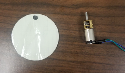
Figure #1 – Materials used to estimate RPMs
Next we used a strobe light at different frequencies to try and estimate the RPM’s of each motor. As the motor rotated, the piece of paper turned and we kept track of the black dot each time the strobe light flashed. When the black dot’s position was the same each time the light would flash, then it was the correct frequency. The frequency of the strobe light was in units of Flashes per minute. Each time the light flashed and the dot was approximately in the same location, then that would correspond to one rotation of the motor. The same experiment was done for the rest of the motors.
Experiment #2
The second experiment was to help determine the no load current, and stall current of each motor. First, we connected a multimeter to a 6v power supply (which was the amount of voltage that is used for the motor descriptions on the Polulu website) in series with the Polulu Motor in order to calculate the amount of current the motor would draw. The first results were for the no load current, where the motor would rotate freely and is the the least amount of current that it is going to draw. Dislcaimer: The following method to test the stall current is not ideal. Other ways to test the stall current can be more accurate while also minimizing effects on the motor. Next, we would hold on to the motor, prevent it from rotating, to calculate the stall current it is going to draw. We then performed these two steps again at a voltage of 3.3v which is around the voltage that the Goliath will be operating at when using the 3Dot board.
As mentioned above, a more adequate way to measure the stall current would be to add more and more weights to the load of the motor until it can not move the mass anymore.
Analysis of Results
The results of the team’s experiment were as follows:
Motor #1 – This motor pulled about approximately 0.04 Amps at 6 and 3.3 Volts. The Stall current that was found was approximately 0.70 Amps at 6 Volts and 0.22 Amps at 3.3 Volts.The RPMs of the motor was calculated to be around 205 RPMs. When looked on the Polulu website for reference, the motor that closest matched our results was the Medium power motor with a 100:1 Gear Ratio and Stall torque of 0.94 Kg x cm
Motor #2 – This motor pulled about approximately 0.11 Amps at 6 Volts and 0.10 Amps at 3.3 Volts. The Stall current that was found was approximately 1.0 Amps at 6 Volts and 0.29 Amps at 3.3 Volts. The RPMs of the motor was estimated to be around 142 RPMs. The motor that matched these specifications on the Polulu website was the High Power Carbon Brush motor with a 210:1 Gear Ratio and Stall torque of 2.8 Kg x cm
Motor #3 – The third motor pulled about approximately 0.110 Amps at 6 and 0.097 Amps at 3.3 Volts. The Stall current that was found was approximately 1.01 Amps at 6 Volts and 0.668 Amps at 3.3 Volts. The RPMs of the motor was estimated to be 125.5 RPMs which approximately matched the Medium Power Motor with a 250:1 Gear Ratio and Stall torque of 3.2 Kg x cm
Motor #4 – The last motor pulled about approximately 0.0142 Amps at 6 and 0.0108 Amps at 3.3 Volts. The Stall current that was found was approximately 0.082 Amps at 6 Volts and 0.094 Amps at 3.3 Volts. The RPMs of the motor was estimated to be 35 RPMs which approximately matched the High Power Carbon Brush motor with a 1000:1 Gear Ratio and Stall torque of 11 Kg x cm
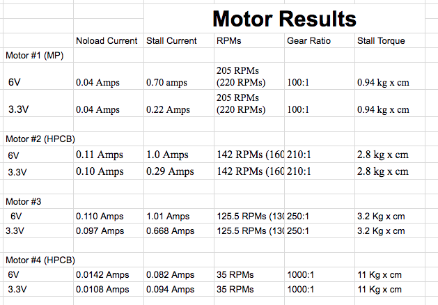
Figure #2 -Results of each Motor at 6Vs and 3.3Vs
After analyzing these results, the team concluded that motor #4 generates a high amount of torque while only supplying a small amount of RPMs. Although his will cause our Goliath to move a high amount of weight, the movement of the robot will be at a very slow velocity. Two other motors (motors #3 and #2) generate a good amount of torque, a range of 2.8-3.5 Kg x cm, but draw a large amount of current which might be a problem with the Goliath’s battery supply. If the Goliath gets stuck or requires more torque from the motors, then the current drawn might even burn out the board. The last motor (motor #1) was the motor which drew the least amount of current while still generating a torque of about 0.94 Kg x cm. Motor #1 is the motor we will be using for future tests on the Goliath.
Conclusion
The overall motor testing was a success, and with the final results of our experiment we were able to find a motor to meet the needs of our Goliath while still maintaining a safe operation point. The team was able to find the motor with enough torque to move the Goliath while not drawing too much current that might drain the battery or fry the board.