Goliath Fall 2017
Gyro and LED Custom PCB
Vanessa Enriquez (Manufacturing Engineer)
Approved By: Mark Huffman (Project Manager)
Introduction
By: Vanessa Enriquez (Manufacturing Engineer)
Approved By: Mark Huffman (Project Manager)
The custom printed circuit board was designed to include both the gyro sensor and the LED display on the top panel. The LED will display the direction the tank is taking within the maze. By working with my project and division manager the schematic and layout were created on Eagle CAD. The files were not submitted in a timely manner to ensure the level 1 requirement that states the Goliath shall be ready by December 13th. The following schematic and layout were submitted on December 1st.
Schematic
By: Vanessa Enriquez (Manufacturing Engineer)
Approved By: Mark Huffman (Project Manager)
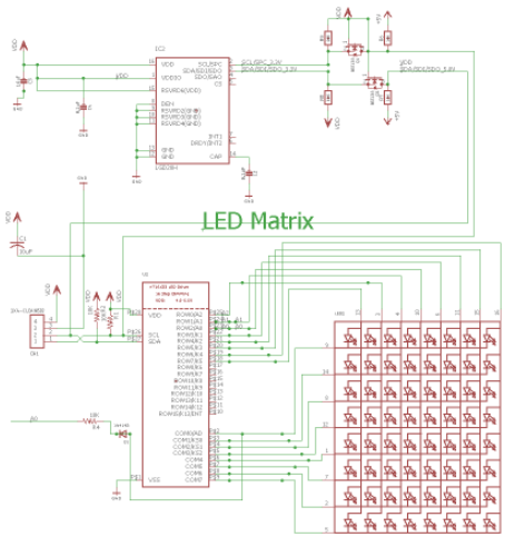
The schematic shown below connects the gyro to the LED grid by clock and data (SCL and SDA) pins. The schematic had several errors in the original files obtained from sources listed[1][2]. Our E & C engineer debugged the schematic and sent it over to be simplified and design the layout.
Figure 1 – Final Goliath custom PCB schematic
Layout
By: Vanessa Enriquez (Manufacturing Engineer)
Approved By: Mark Huffman (Project Manager)
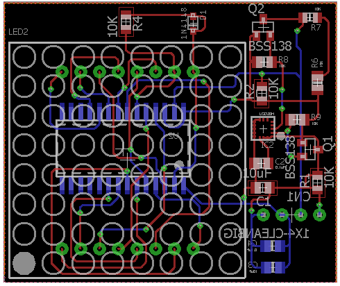
The first step was to measure the dimensions for the PCB based on the location we decided. The LxW dimension is 45×38 mm. The two-sided board will include the LED grid on the top and the gyro IC2 on the bottom. To simplify the design, I created a VDD polygon at the top layer and a GND polygon at the bottom layer. After connecting all of the wires, the default 2-layers and the 3-dot 2 layer (tight) design rules were loaded and checked. It is worth mentioning that the tight design rules require an 8 mil. wire width opposed to the default 6mil.
Figure 2 – Final Goliath custom PCB layout
Unfortunately, this design was not approved by professor Hill, in part because of the late submission. The next step would have been to order and assemble the PCB and test it.


