Goliath Fall 2018 Design
Author/s: Josephine Tjandra and Felix Velasquez
Table of Contents
Introduction
For the Fall 2018 Semester, the Goliath project was a redesign of the Goliath from Generation #2. We took the basic structural design of the robot and incorporated a new motor/gear system, as well as other modifications. The design of the Goliath of Generation #2 had small deficiencies that need to be corrected before it can run and function efficiently. In this blog post we will outline the deficiencies that Goliath #2 had as well as our new additional design incorporation.
Design Flaws
By: Felix Velasquez
Small Idle Wheels and Track Friction
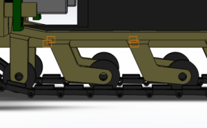
The Generation #2 Goliath has small idle wheels that help align the tracks, but they cause a lot of friction which requires more torque from the motors. The extra work that the motors output results in more current being drawn which drains the battery life quickly. The current design for the idle wheels in the Goliath is shown in the figure below.
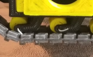
When the model is actually 3D printed, connecting the wheels to the side panels is not that easy and the wire that is used to connect the wheels hangs out and hits the tracks as seen below.
In addition, the tracks are too close to the side panels which adds more friction each time the tracks and the side panels touch. When turning, the constant interaction between the panels and the tracks cause the tracks to be lifted out of place of the driving sprocket and then fall out of place which brings the Goliath to a stop.
In addition to the friction, the small idle wheels do not have a proper way to connect them to the Goliath. The current method of attaching them to the Goliath is by cutting small pieces of wires and hooking the wheels with the robot. As seen in the figure below, the current method is not effective because the excess wire that is left over hits the tracks each time the wheels turn which causes more friction for the motors to overcome.
Latching/Support System
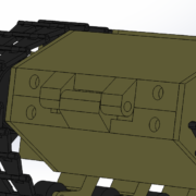
The current latching system that the Goliath has for the top and bottom panel to connect does not work correctly. The panels have small, circular, hollow shafts at one end that would hold the panels together when a piece of wire or small nail is inserted. This design was not modeled correctly because the shafts do not fit correctly and would have to be forcefully connected. Currently, the top and bottom panels just lay on top of one another and are not connected. In the figure below we see the current latching system the the Goliath design has.
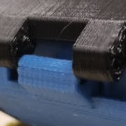
When the Goliath gets printed and built, the actual latching does not physically level-up, or match up, and therefore they can not be connected correctly. In the next figure, we can see how the latches shafts are uneven and therefore a wire or nail cannot fit through them without force which may cause it to break.
3D printing
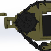
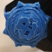
Finding a location to 3D print the goliath was another challenge that the team had to overcome when prototyping. Some small pieces of the robot had details that were not printed correctly and required to be printed again. One example of this is the driving sprockets of the robot. The triangular teeth at the end of wheel (the ones that grip the track in order for them to move) didn’t print correctly in one of the printing locations [5] we first went to. Although the 3D printing is not a direct defect of the design, improvements in the design can facilitate the 3D printing. In the figures below we can see the SOLIDWORKS model of the driving sprocket, and in the one below it of the actual 3D print.
Redesign
By: Josephine Tjandra
Body Dimensions
The Goliath will include the 3Dot board to control the motors as well as the code for the mission fo the Goliath. Based on the fact that we wanted to modify the Goliath to fit the 3.5 x 7 cm 3Dot board snugly and overall make the Goliath as small as possible, our initial dimensions are 11.37 x 7.78 x 4.58 cm.
Goliath 302 Tank Dimensions: 1.5 x 0.85 x 0.56 m
Determining Goliath Ratio with reference ratio 1.5 m:
L = 1.5/1.5 = 1
W = 0.85/1.5 = 0.567
H = 0.56/1.5 = 0.37
Ratio: 1 x 0.567 x 0.37
Our ideal F’18 Goliath dimensions based on the ratio would be 11.37 x 6.45 x 4.21 cm based on the calculations below:
L_ideal = 11.37 cm
W_ideal = L_ideal * Width Ratio = 11.37 * 0.567 = 6.45 cm
H_ideal = L_ideal * Height Ratio = 11.37 * 0.37 = 4.21 cm
Comparing our ideal and actual dimensions, we can find the percent error for the length, width, and height:
%L error = |(L_ideal-L_actual)/L_ideal|*100 = |(11.37-11.37)/11.37|*100 = 0%
%W error = |(W_ideal-W_actual)/W_ideal|*100 = |(6.45-7.78)/6.45|*100 = 20.6%
%H error = |(H_ideal-H_actual)/H_ideal|*100 = |(4.21-4.58)/4.21|*100 = 8.8%
Our final dimensions are slightly larger than the ideal dimensions because we are leaving room for the motors in the side panels as well as the new gear system which we will discuss in this post.
Gear System
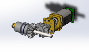
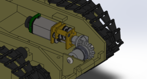
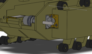
To eliminate unnecessary space, we moved the motors to the open compartment in the side panels of the Goliath. By doing so, we were not able to connect the driving wheel directly to the shaft of the motor as it has been in previous Goliaths. To compensate for this issue we added a new bevel gear system that was designed by Jeff Gomes. The motor will sit in the side compartment and its shaft will connect to a gear. That gear will drive another gear that is on the same shaft as the driving wheel, causing the wheel to move. The photos of the gear system and how it will fit into the Goliath are shown below.
Bottom and Top Panel Modifications
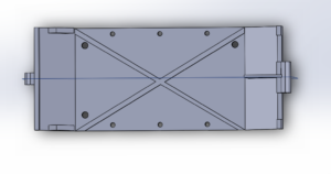
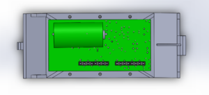
For the bottom and top panel, the length remained the same but by moving the motors, we were able to make the width of the two panels from 53.98 mm to 43.27 mm. The motor compartments were removed from the bottom panel to make room for the gear system as well. We also added a ribbing, which is the X on the panels, to help with the structural strength of the panels. Shown below is the bottom panel with the ribbing feature and also how the 3Dot will fit on the bottom panel more snugly. We are also working on a better latching system to connect the top and bottom panel together and also to be more secure.
Side Panels Modifications
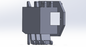
For the side panels, we closed the side doors that in the previous generation would open up as a sensor, as we will not be needing it anymore because the mission of Goliath has changed. There was also the design flaw mentioned that involved the tracks being slightly too close to the side panels, creating more friction because it would rub against the panel. To fix that, we moved the wheel holders slightly out, roughly 1 mm. We also had to create an opening in the side panel to make room for the gears and the motor to connect to the driving wheel. Because the length of the side panel stayed the same, we did not have to worry about making sure the tracks would fit, allowing us to use the same set of tracks as the past generation. We also are working on a better way to attach the bottom and top wheels on the side panels. Shown below is the opening made and how the gear fits, and also the closed side doors.
Overall Improvements
Overall, the design modifications that we made to the Goliath included moving the motors to the side compartments, resulting in a gear system added. We had to make room for the gears by making an opening in the side panel. We also shortened the width of the bottom and top panel to fit the 3Dot board better and also added ribbing to strengthen the structure. We are still working on a better latching system and a better way to attach the small wheels on the side panels.

