Goliath Spring 2018 – Line Following Code
By: Tai Nguyen (E&C Engineer)
Verified By: Ernie Trujillo (Project Manager)
Approved By: Miguel Garcia (Quality Assurance)
Introduction
The Goliath tank is using (2) IR sensors on (2) Adafruit SI1145 to line follow. The SI1145 doesn’t have an IR LED on it, so an external 850nm IR LED bought from Everlight through Digikey is used to produce the infrared light. The SI1145 is an I2C addressing device, therefore they share the same I2C address at 0x60. To resolve this issue, the PCA9540B 2-channel I2C multiplexer is used to communicate to both devices. For testing purposes, the TCA9548 multiplexer was used.
IR Sensing
Infrared sensors work by using an LED to emit infrared light and then having a sensor that measures the intensity of the reflected light. Lighter colors will tend to reflect more IR light while darker colors will tend to absorb IR light, thereby reducing the amount of light reflected. Due to the UV sensor not having its own IR LED, we had to look at the wavelength graph on the SI1145 datasheet to determine the range of wavelengths the sensor can read.
In the graph, at the peak of the IR Photodiode, we see that the range of optimal wavelength values is from 750-850 nm. The 850nm was the most common IR LED and the cheapest, so it was chosen for the test.
Test Setup
I hooked up the LED to a digital pin on the SparkFun Pro Micro and showed it downward side by side to the IR sensor. After adjustments, I found the optimal height above the surface you’re measuring to be ¾ inch. This gives you a clear 100-200 LSBs between reading a black surface and a white surface.
Line Following Algorithm
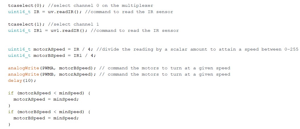
If you notice, we send the motor speed to the opposite PWM output. This way, we can easily control the motors based on what the IR sensor is reading. The way black line following works, we want the motor that is not seeing white, to speed up to return the sensor to the black line. This solution was only implemented however because of the way the IR sensor was soldered to the protoboard. IR1 was on the side of motor A and IR was on motor B. If we swap these sensors, we wouldn’t have to swap the PWM outputs.
Example:
IR1 reads a value of 1000, and IR reads 300. According to this, we know that IR on channel 0 is reading black while IR1 is reading white. We’ll need to tell the motor on theIR1 side to speed up and return back to the line. We also want IR0 to slow down to assist IR1 to return quickly in order to correct the robot before the next intersection.
Conclusion
Line following has been done by many colleges and projects, so there are plenty of resources to assist many beginners. If robots use IR sensors to navigate through a maze, the maze would be required to have lines in the middle of pathways for robots to follow. White surfaces reflect more IR light back into the photodiode and black surfaces will tend to absorb the light, reflecting less back, resulting in a lower LSB value.


