Goliath Spring 2018 – Turning Method
By: Tai Nguyen (E&C Engineer)
Verified By: Ernie Trujillo (Project Manager)
Approved By: Miguel Garcia (Quality Assurance)
Table of Contents
Introduction
The turning method of choice was turning using a gyro. The gyro we chose was the SparkFun Triple-Axis Digital-Output Gyro Breakout – ITG-3200. This specific breakout features an I2C serial interface, optional external clock, and digital outputs for X, Y, and Z axis angular rate sensors. The VDD supply voltage ranges from 2.1-3.6V. We ran tests using a 3.3V VDD from the SparkFun ProMicro 3.3V 8MHz.
How does a Gyro Work?
Before getting started, it is important to know how a gyro functions and how to use it. A gyro measures angular velocity, the rate of change of the angular position over time, which is usually given in degrees per second on the datasheet. If you want your robot to turn a certain amount of degrees, for example, a 90-degree angle, we would not need the angular velocity, but angular position. From Calculus I, we know that the derivative of position is velocity. To obtain a position from velocity, we will need to perform an integration.
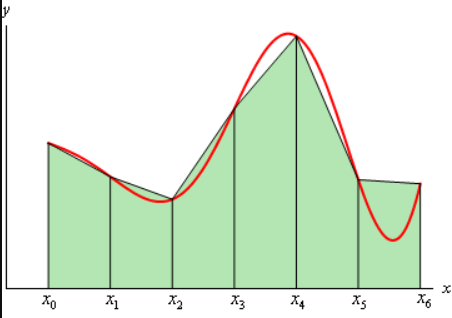
An integration involves your variable multiplied by some delta time. Most people know of integration as an “area under the curve” and to solve for more parabolic curves, techniques like left-side, right-side, midpoint, or trapezoidal integration come to mind, where it is a sum of multiple areas across a delta time. In digital systems, it is very difficult to perform continuous integration, so the simpler solution is to take a sum of finite delta angles over delta t.
Initialization code
These are global variables created outside of void setup() and void loop(). The first variable is a float data type to achieve the best accuracy when it comes to integrating (the closer we can get to 90 degrees ex: 90.039 degrees, the better). We also want a static variable qualifier to preserve the angle data as we slowly add each delta angle loop after loop. The variable then is what is going to keep track of how much time has passed since call of the millis() function, which stores time passed in milliseconds. tSpeed is a constant to determine our turn speed for our motors. zRate is a SIGNED 16-bit variable that records the angular velocity.
Main Code
A common issue with any gyro that must be fixed is drift. When your gyro is sitting still, there is an offset or an error that occurs. Try plugging in your gyro and reading the angular velocity while it is sitting still. That is your error for that axis. Over time, this angle offset will add up to multiple turns/rotations and that is what drift is. There are 2 ways you can try and solve this issue. One way is to first notice that your error tends to jump around, like for example, you’re reading the zRate and it’s displaying 5.25, 5.06, 5.78, 5.60, 5.80 and etc. The error is not a constant. So the method to get a singular constant error would be to run a 20 point average. A running average takes N points of data and finds an average. To do this, you would apply a for loop.
Here is an example that sums up each point of data using a for loop. After you find the sum, create a new variable and divide that sum by N amount of points that you recorded.
After you get this term, when you record your zRate, subtract this offset value and you’ll achieve a near 0 value when you’re not moving.
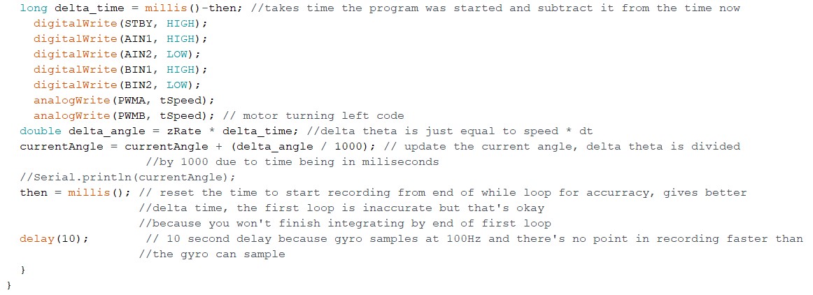
The second way of calibrating your velocity offset is to apply a hysteresis (double threshold) with if statements. Figure 2 shows if statements that say, if the speed is less than +2 and greater than -2, then the gyro is not moving and to set the angular velocity data = 0 degrees/second for that reading.
Uncomment the Serial.println(currentAngle) to test and track how many degrees your gyro has rotated.
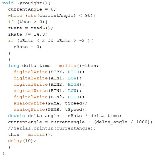
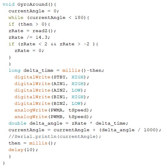
Below is the turning code for right turns and turning around:
Conclusion
Gyros are great tools that have applications such as orientation measuring or turning. A gyro outputs an angular velocity which we use to determine angular position through integration. In almost every gyro, there is an error that accumulates over time called drift. Drift occurs when the gyro rotates faster than you can sample and so your integration approximation is going to be incorrect. Integration in digital systems are never 100% accurate so there will always be some small error in the end.
References
- https://www.sparkfun.com/products/11977
- http://tutorial.math.lamar.edu/Classes/CalcII/ApproximatingDefIntegrals_files/image002.gif


