Grad Bot, Fall 2019
Conceptual Design/ Proposed Solution:
The Dos and Don’ts of GradBot
Author: Shannon Hormozian, MST, PM
Verification:
Approval:
Table of Contents
What We Learned
GradBot was originally designed to have two modes which would have been selected in the Arxterra App. One mode would work like a stereotypical controlled toy, using two digital toggles, one for forward and backward motion and one for left and right movement, giving the user the power to move the robot in any direction. The second mode would be a follower option. This option would have had the robot follow the user with about a 2 to 3 foot gap between them. The follower portion would be implemented using an accelerometer and gyroscope connected to a GPS module inside the robot which would then connect to the Blynk app and keep the robot within 3 feet of the user holding the phone.
First Challenges: V1 Demo
Our V1 demo brought up some issues we hadn’t come across when testing at home. We found that having all of the group projects in the class use the v9 board from the paper bot kits made it almost impossible to connect our specific phone with the ArxRobot app to our specific v9 with an HM-11 BLE module. While testing in preperation for the demo, we tried to connect multiple times and most of the tests the connection would time out due to the overwhelming about of Bluetooth capable objects popping up. For one test we even accidentally connected to another groups project and were moving their motors with our app.
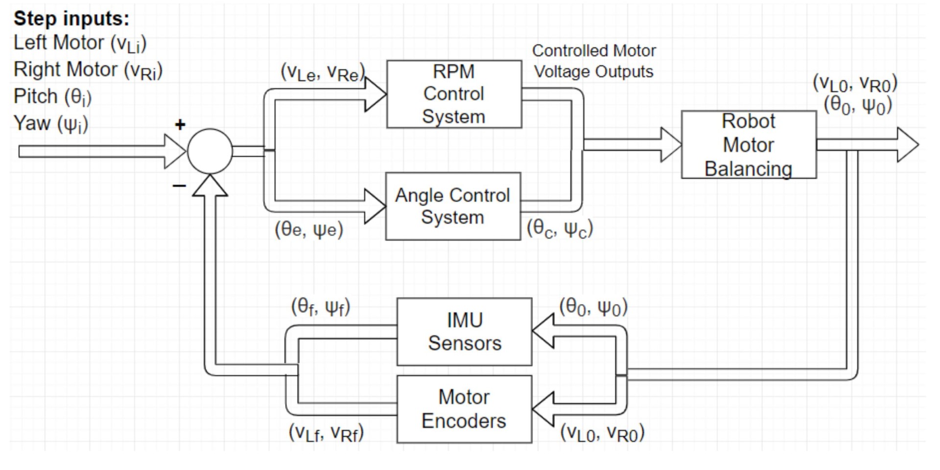
The next issue, and arguably the most important, came with GradBot’s movement. While in motion, the robot would lean from side to side giving it an unbalanced appearance. The solutions that were thought up and discussed were to include an active damping PID controller with motor encoders. The controller was supposed to gather information from the motors and from an added gyroscope and then feed this information back into the system to correct any changes in balance.
To view our V1 Demo, click here.
More Solutions, More Problems
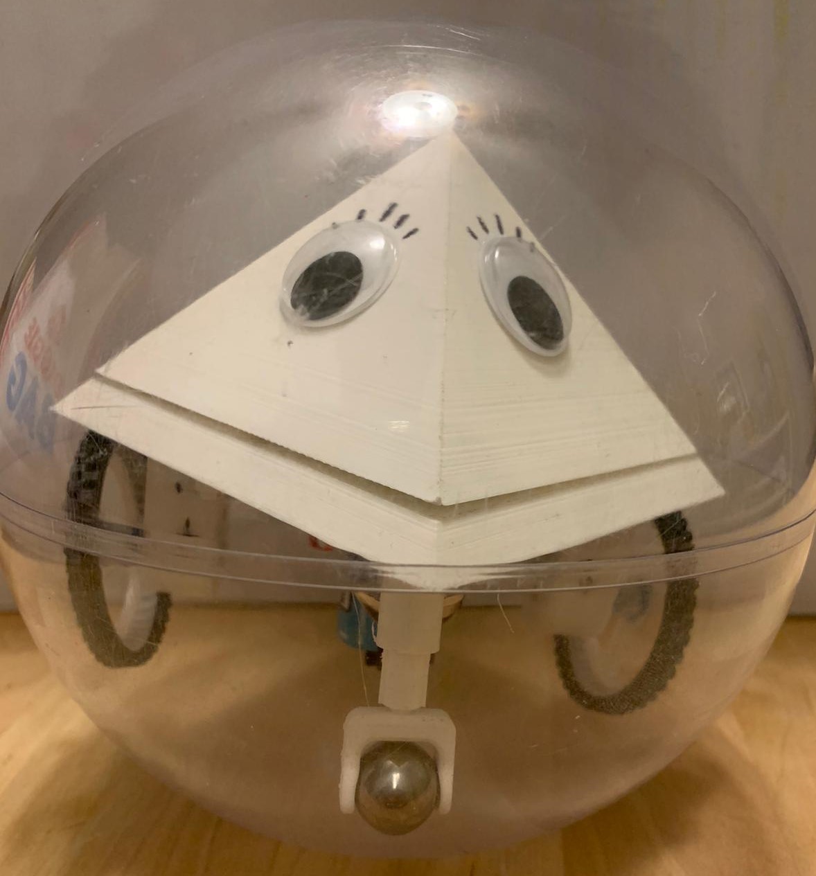
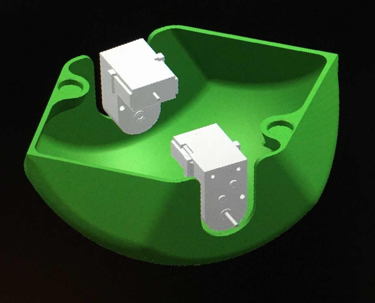
For v2 our “quick fix” for the balance was to add a rounded base to the pyramid to add stability and lower the center of mass. Our goal for the base was to have it match almost perfectly to the inside of the clear sphere and a subtracting function was used to accomplish this in the modeling program.
To view our v2 demo, click here
The base ended up working much in our favor, but it did not completely solve the balance issue. A PID would still be needed.
System Design
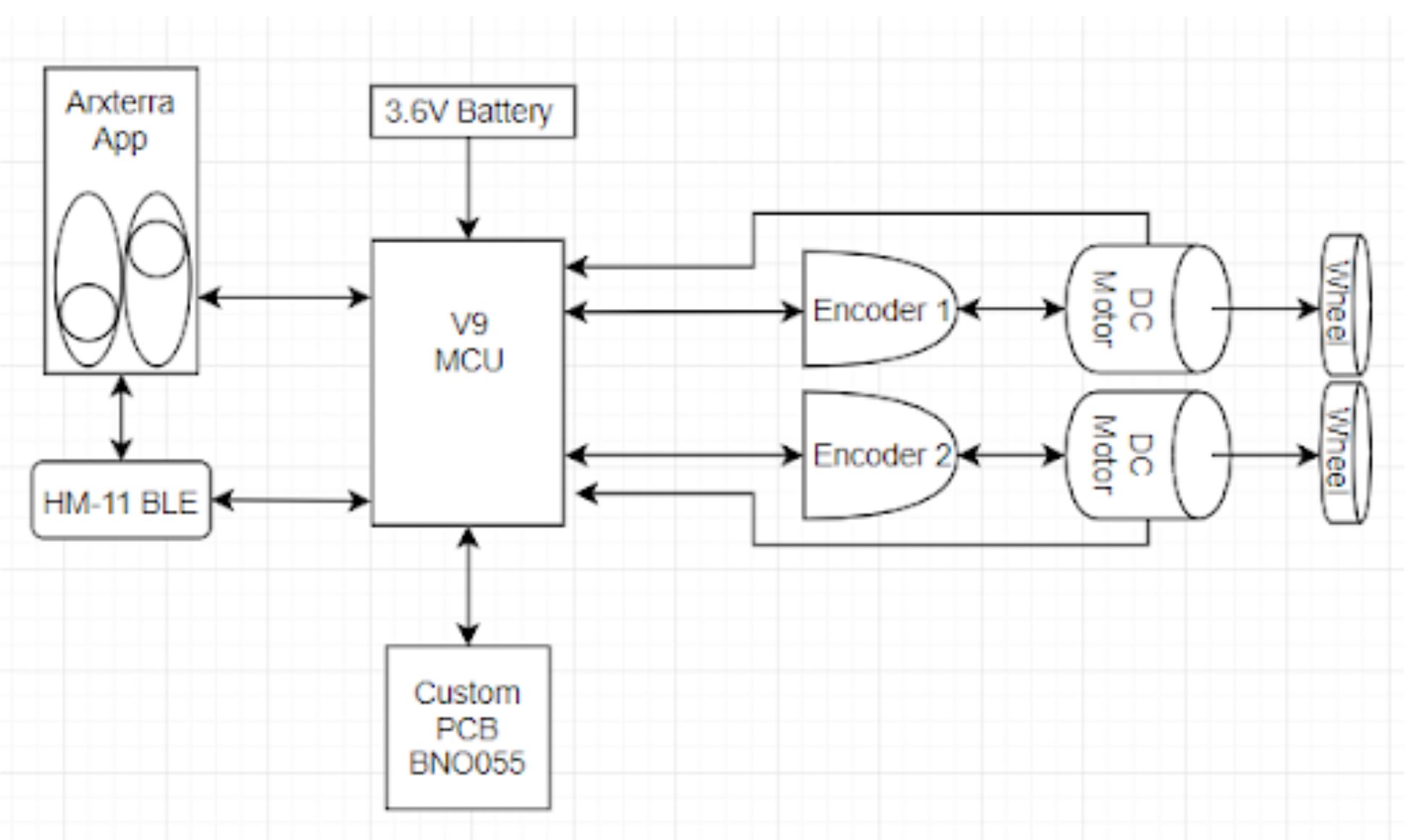
For the PID system to be implemented we needed an IMU which included an accelerometer and a gyroscope, as well as quadrature motor encoders. The encoders would gather measurements from the motors and the gyroscope would take measurements of the roll (wobble from left to right) and pitch (roll from front to back). All of this information would be plugged into a correction equation and sent back to the encoders and the board which should adjust the motors accordingly.
The entire system would work cohesively as one to give us a moderately balanced robot.
Conclusion
Even though we accomplished many of the things we originally had in mind, the PID we tried to implement this semester didn’t work out in the end. We ran out of time and resources, as unfortunate as it sounds. We got extremely close, we have a preliminary design for a PCB and some basic ideas on how we would have implemented the controller which can be found on the PID Firmware blog post.


