GradBot – Fall 2019
3D Models & Prints
Author/s: Taylor Manning, D&M
Verification:
Approval:
Table of Contents
Introduction
GradBot, a new conceptual project for 400D, consists of six mechanical designs: Pyramid, Spherical Cover, Graduation Cap, Graduation Cap Support, Tires/Wheels, and DC Motor Mounts. Through the process of rapid prototyping, many of these pieces underwent critical design changes. Below is a full description of each part, its function, and purpose of design.
Pyramid Design
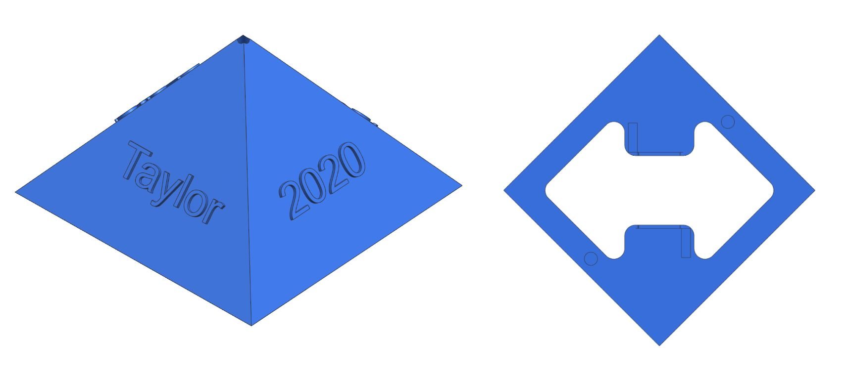
Figure 1. 3D model of pyramid body for GradBot 2.0
The pyramid, in its final form, is mechanically one piece. With our names and graduation year embossed on the side for aesthetics. The pyramid shape itself is a standard shape that can be created in any CAD program, however, we added a hole in the top for a spindle that will hold and support the Graduation Cap Support. The bottom of the pyramid consists of a little more innovative design as we had to determine how to lessen weight to prevent it from being top heavy, all the while creating a mechanical mount space for the DC motors.
Design Iterations for Pyramid:
- First rapid prototype brought us a pyramid that had a sliding side panel for access to the inside of the pyramid in order to house the electronics. We quickly realized that this method would be unsuitable due to the size of the V9 board and any other components that would be needed. It also was a poor design for balance as it prevented the V9 from beingcentered in the pyramid itself.
- Rapid prototype design number two brought us a pyramid body that would split in two. The top and the base. This way we would have more access to the entire inside of the pyramid for potential electronics configuration. This is where the idea of magnetically attaching the two pieces was born and two slots for magnets to be seated in were attempted to be incorporated into the design. We still had issues with how to place the V9 in the pyramid (this we figured out in the CAD model) but this design put us on track for what to implement in our final design. Note: Due to the restrictions of the pyramid shape (the slope of about 51.5 deg) embedding magnets became a significant challenge that will be solved in later iterations
- Rapid prototype three we decided to try and center the weight and drop it below the pyramid to aid in stability. Up to this point the robot would tumble in the sphere due to imbalance and poor weight distribution. To do this, a cutout in the shape of the V9 was made into the base of the pyramid so that the battery would hang below and drop the center of mass. This way the board was not preventing the pyramid from closing properly either. To fix the magnet positioning issue, a cylindrical type shape was united into two corners of the pyramid top that would allow us to create the depth needed to house a magnet. The same holes were created in the pyramid base to line up accordingly. This prototype we built and tested in our v1 demo with successful demonstration of our concept. Note: Balance was still our main issue. We experienced significant wobble and surging as the weight distribution needed improvement and the wheels that we were using we not best suited for the inner curvature of the sphere. The wheel problem and solution will be explained later.
- In our final iteration of the pyramid design, we no longer separated the pyramid in two. As you can see in Figures 1 and 2, the Pyramid is one piece with the center of the bottom cored out to lessen weight. The pattern seen arises from leaving surface area to mount the DC motors and inadvertently provides inner ledges in the pyramid to mount small electronics if deemed necessary. Otherwise now the spherical cover (which will be discussed later) will house a majority of the components so as to effectively drop the center of mass to the very bottom of the outer sphere. In this final iteration is also where we added the names of the group members and our graduating year for aesthetic flair.
Electronic Housing Design

Figure 2. Electronic Housing
The spherical cover is also mechanically one piece. It will be a housing with two magnets, two bearings with a “dog-ear” type fastening so the bearings to stay in place, slots to insert all electronics into, slots so that the wheels can peak through and still drive the robot, and open space at the bottom for additional weight. The magnets will be used for attachment to the rest of the robot and the bearings will provide stabilization within the outer sphere.
This design was a challenging considering it had to match the bottom shape of the pyramid and then be contoured into the shape of a sphere. The next challenge was creating the places for the wheels and bearings to come through so they could aid in the balance of the pyramid and allow for it to still create forward motion.
Design Iterations for Electronic Housing:
- The first model created had a square opening that matched the contour of the pyramid’s base and gradually transitioned into a spherical bottom. This allowed for better stabilization and provided ample room on the inside for the electronics and the ability to conceal the wheels. Only downside to fitting the wheels internally into the sphere was lack of easy assembly. By the way we oriented the wheels on the pyramid (at 45 degrees so that the wheels would sit out farther) there was no way to have them slide in once the wheels were mounted on the pyramid base. This brought about the updates seen in the final model of the housing.
- The final electronic housing featured a new sleek body design that keeps the wheels on the outside and could allow the assembly to more smoothly slide together. By creating these slices, we were able to reduce weight and keep it still looking aesthetically pleasing.
Graduation Cap Design
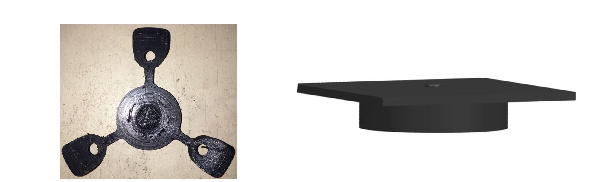
Figure 3. Grad cap mechanism and total assembly
Designing the mechanism that would sit atop the sphere in order to mimic that Mortar Board style graduation cap was not as complicated as we once thought. It was by no means simple, but with some advice, we were able to use the sphere model we already had to make the perfect mold in the graduation cap base. By starting with a short solid cylinder, we were able to inlay the sphere model into it and use a subtract function to give us a perfect concave to match the outer diameter of the sphere. From here we needed to design inserts for bearings and magnets so it would reduce friction on the surface and have a way to stay on top of the sphere in motion. We decided to place magnets approximately 120 degrees apart. We also decided to reduce the model down to the image you see above to shed unnecessary weight to improve the graduation cap’s ability to stay on top of the sphere and allow the robot to move.
Design Iterations for Graduation Cap:
- The original graduation cap mechanism was a semi-solid piece that when printed looked like the full formation of a graduation cap. This worked well and aesthetically looked the part. However, this piece with the bearings and magnets embedded was too heavy and threw the entire robot off balance regardless of the counter balancing weight we put inside the robot assembly.
- In the second iteration, we mimicked the graduation cap support so that it was just a 3-armed spindle with the same contour as the first iteration of the graduation cap. This significantly reduced the weight. We also reduced the weight by using either card stock or foam board for the mortarboard part of the cap and card stock for the cylindrical head piece. In preliminary testing of this new design, result were promising.
Graduation Cap Support
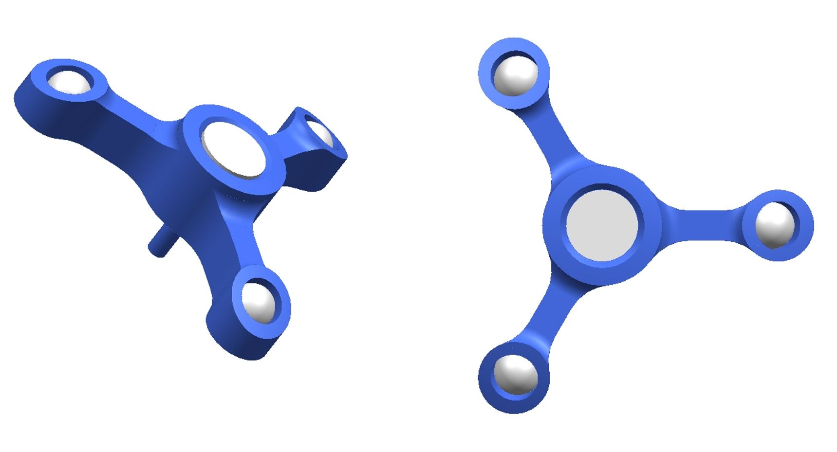
Figure 4. Internal mechanism for the cap
Designing the mechanism that would sit inside the sphere was very similar to the design of the graduation cap piece. We had to create a part that would match the center magnet in the cap and fit to the inner diameter of the sphere. With some advice, we were able to use the sphere model we already had to again make the proper contour to the part. By starting with an extruded triangle, we were able to overlay the sphere model onto it and use a subtract function to give us a perfect convexed shape to match the inner diameter of the sphere. From here we needed to design an insert for the magnet so this part could be used to magnetically hold the graduation cap normal to the top of the sphere. Bearings were set 120 degrees apart to match the graduation cap bearings and excess material was subtracted away to make the part lighter. A small hole was created in the center so a shaft could be placed in the center for attachment to the pyramid with a spring to create tension and downward force on the wheels.
Tires/Wheel Design

Figure 5. Final print of wheels
Originally, GradBot was going to utilize the tires/wheels that were provided in the 3dot kit for the sake of saving time and resources. However, we soon realized that using those tires would no longer be sufficient with only one edge of the tire making contact at any given time. This inhibits the motors ability to propel the robot forward efficiently and induces a wobble because the wheels grab the surface at different times. To mend this, we created a sturdier wheelbase that could better withstand the weight of the pyramid body, as well as created a slanted tire that will have more surface area in contact with the inner part of the sphere at any given time. We kept the wheel/tire approximately the same diameter as the ones from the 3 dot kit because the height matches well with where the pyramid needs to be positioned in the sphere. Instead we thickened the tire to accommodate for the angled slant and provide more surface area in contact with the sphere. The inner part of the wheel is hollow to create more traction when the weight of the robot is pushed down onto them.
DC Motor Mount Design
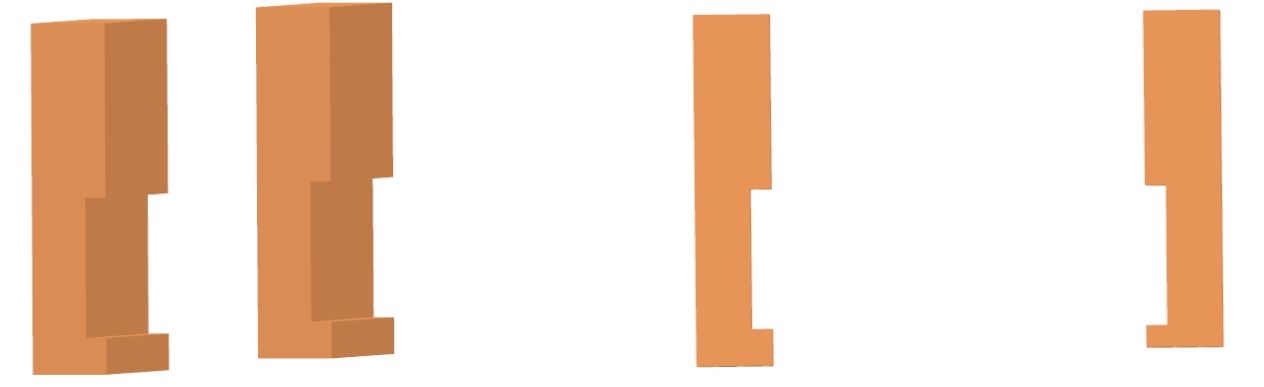
Figure 6. Motor mounts
In order to mechanically fasten the DC motors to the bottom of the pyramid, we created slots in the base of the pyramid for our motor mounts to slide into that will match the profile of the wire harness side of the motors. These were a simple addition to the robot in order to mount the motors where they need to be for best fit in the sphere.