HeroBot Summary Blog Post
Author/s: Steven Marsella
Verification:
Approval:
Table of Contents
Executive Summary
HeroBot is a bipedal robot tasked within retrieving a key card placed with the Paperbot maze and escaping in the shortest amount of time possible. HeroBot shall use four main sensors to achieve this task: a radio frequency identification (RFID) sensor for detecting the key card, an inductance to digital converter (LDC) for boundary detection, an infrared (IR) sensor for room detection, and an inertial measurement unit (IMU) for turning.
Program and Project Objectives
Program Objectives
The Robot Company (TRC) aims to design a self-balancing robot to compete in a competition. The competition consists of exploring an unfamiliar territory while fending away monsters using equipment scattered around the terrain and possibly retrieving loot before returning to the robot’s starting location.
Project Objectives
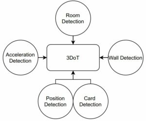
TRC’s HeroBot seeks to build upon the Humans for Robots 3DoT robot by adding additional functionality, such as self-balancing, card reading, room detection, wall detection, and turning.
Mission Profile
The original mission statement required HeroBot to be a self-balancing robot who explored an unmapped maze filled with unique monsters, treasures, and weapons. HeroBot would begin from a designated starting location and return to that same location after acquiring loot and/or defeating monsters.
The updated mission called for HeroBot is to retrieve a key located inside the maze before exiting through a designated location without using a predetermined/linear/stack of moves.
The original maze project definition can be found here and the updated maze project can be found here.
Project Features
HeroBot is comprised of three main systems communicating with the Humans for Robots 3DoT board to successfully complete its mission:
- card reading
- controls, and
- navigations.
The card reading system will detect the key card, the controls system will detect the robot’s acceleration and position in space for turning, and the navigations system will detect rooms and boundaries for path following.
Requirements
TRC’s HeroBot will adhere to certain requirements to meet its application needs. These requirements are further explained in the sections below.
Engineering Standards and Constraints
Applicable Engineering Standards
L1.201 – The robots shall contain one or more custom designed 3DoT shields. The 3DoT shield(s) incorporates interface electronics between the 3DoT board and sensors and/or actuators unique to the robot. Due to COVID 19 restrictions, each engineer shall submit a custom functional SMD based PCB with the exception of the game software engineer.
L1.202 – Assembly and basic functional testing of the robot shall be constrained to less than 20 minutes.
L1.203 – Due to COVID-19 restrictions, each team member will construct their own 3DoT robot. The cost of each completed robot will not exceed $250.
L1.204 – Team member robots will be completed by the date of the mission (i.e., starting the week of May 9, 2021). Project completion includes all documentation and capability to execute the mission.
L1.205 – The mass of the robot will not exceed 300 grams.
L1.209 – Software will be written in the Arduino De facto Standard scripting language and/or using the GCC C++ programming language, which is implements the ISO C++ standard (ISO/IEC 14882:1998) published in 1998, and the 2011 and 2014 revisions.
L1.210 – The assembled robot chassis dimensional envelope will not exceed 6″ width, 8″ height, and 5″ length.
L1.211 – The robot will use the 3DoT v9.05 or later series of boards to achieve the mission objective.
Environmental, Health, and Safety (EH&S) Standards
L1.206 – Power to the robots will be provided by the 3.7V Li-Ion battery included with the 3DoT board, with a capacity of 700 mAh (min) to 750 mAh (max) and a power rating of 2.59 (min) – 2.775Wh (max) (included with the 3DoT board). Use of an external battery will use a 2.0mm PH series JST connector located on the 3DoT board and covered in a separate requirement.
L1.207 – All safety regulations as defined in Section 4.3 Hazards and Failure Analysis of this document will apply to the shipping, handling, storage, and disposal of LiPo batteries.
L1.208 – The diameter of power-carrying wires will follow the American Wire Gauge (AWG) standard.
Program/Project Level 1 Requirements
L1.001 – The robot shall participate in a competition as defined in the “Rules of the Game.”
L1.101 – The robot shall autonomously navigate the maze.
L1.102 – The robot should win the competition.
L1.103 – The robot shall enter and exit the maze at the entrance and exit indicated by the Game Master.
L1.104 – The robot shall traverse the maze without passing over any boundaries or impacting any physical walls.
L1.105 – The robot shall find the key before exiting the Paperbot (i.e., standard) maze.
L1.106 – The software program shall not utilize a predefined list of instructions, contained in code, data table, or other data structures to execute a series of hardware actions to achieve the mission objective.
L1.107 – The robot shall be able to make 90 and 180 degree turns.
L1.108 – The robot shall detect when it enters a new room. This requirement can be met concurrent with other maze traversal requirements.
L1.109 – The robot shall detect the walls (i.e., hedges) of the room it is currently in.
L1.110 – The Paperbot maze will have a grid spacing (i.e., dimension of a square) of 2.861’’ x 2.861’’.
L1.111 – Each room in the Paperbot maze will have a minimum distance of 2.25” from one black line to the opposite.
L1.112 – Thickness of black lines will have a width of 8 pts (2.82 mm or 8/72”).
L1.113 – The robot will be built using the provided wooden-chassis in Humans for Robots 3DoT robot kit.
L1.114 – The key card provided here (your choice), will be placed in the center of a room in the maze provided here. The Game Master will specify the location of the card, concurrent with the definition of the entrance and exit from the maze (reference L1-103).
System/Subsystem/Specifications Level 2 Requirements
The derived design requirements below originate from the program/project requirements; they are division-specific.
Card Reading
L2.001 – The robot shall have a top shield that is used for card detection.
L2.004 – The key card will be modified such that an RFID tag is attached to it.
L2.005 – The robot shall use a custom PCB which reads RFID to determine the presence of a keycard.
Controls
L2.006 – The robot shall use an IMU for turning.
L2.008 – The robot shall be able to determine its orientation/cardinal direction using the IMU PCB, corresponding to the north, east, west, and south.
L2.009 – The robot shall turn at a 90 degree angle using an IMU.
L2.010 – The robot shall be able to turn at an 180 degree angle using the IMU.
L2.002 – The robot shall have a front shield that is used for room and wall detection.
L2.003 – The robot shall have a top shield that is used for turning the robot 90 and 180 degrees.
L2.011 – The maze will be modified such that 1/4″ strips of copper tape are placed directly underneath (on the bottom side of the maze) the black lines on the walls and hedges.
L2.012 – The robot shall detect strips of 1/4 inch wide copper tape, as dictated by L1.03 and L2.03.
L2.013 – The robot shall detect the IR sensors to detect the start of a new room, as dictated by L1.13 and L2.03.
Project Report
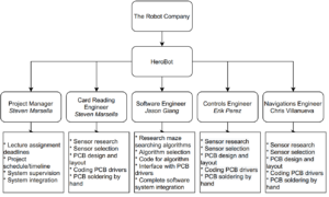
The work breakdown structure describes the hierarchical work the engineers need to do to accomplish the program goals.
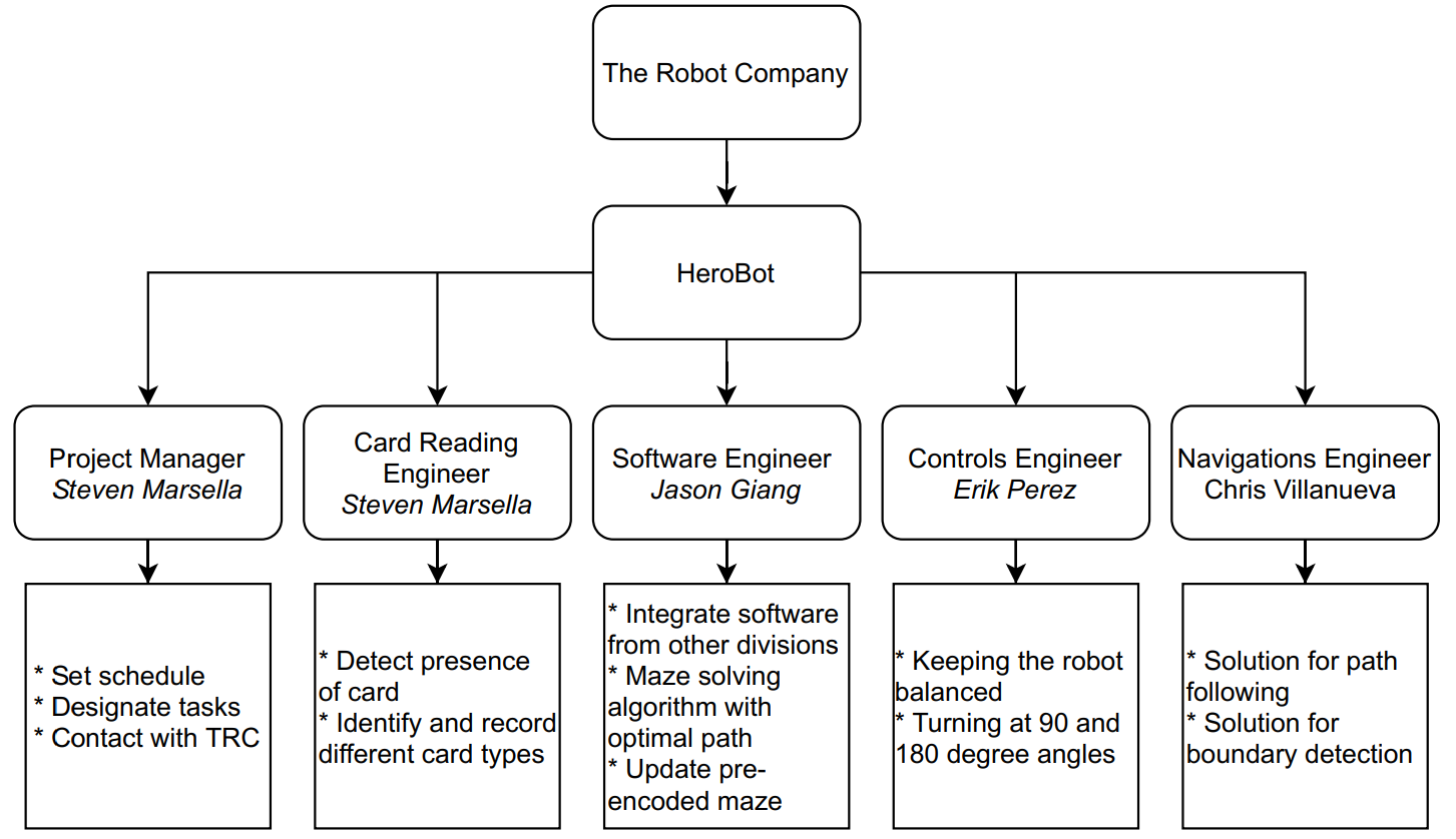
The product breakdown structure describes specifically what each engineer is tasked with doing to accomplish their task.
The HeroBot team is composed of four engineers:
| Steven Marsella | Project Manager, Card Reading Engineer |
| Erik Perez | Controls Engineer |
| Chris Villanueva | Navigations Engineer |
| Jason Giang | Game Software Engineer |
Project WBS and PBS
Work Breakdown Structure (WBS)
Product Breakdown Structure (PBS)
Cost
| Component | Value (if applicable) | Manufacturer Part No. | Quantity | Unit Price | Total Price |
| Capacitor | 0.1uF | UMK107B7104MAHT | 10 | $0.04 | $0.44 |
| Capacitor | 10uF | LMK107BBJ106MA8T | 10 | $0.20 | $1.96 |
| Resistor | 100 | GWCR0603-100RFT5 | 12 | $0.10 | $1.20 |
| Resistor | 1K | GWCR0603-1K0FT5 | 12 | $0.10 | $1.20 |
| Resistor | 10K | CR0603-FX-1002ELF | 12 | $0.01 | $0.08 |
| Molex Connector | Female | 528080470 | 12 | $0.28 | $3.31 |
| IMU Sensor | MPU6050 | 1 | $6.95 | $6.95 | |
| PCB Fab Service | JLCPCB | 1 | $10.00 | $10.00 | |
| Stencil | JLCPCB | 1 | 7.05 | $7.05 | |
| Hot Plate (for solder) | Amazon | 1 | $16.95 | $16.95 | |
| Solder Paste | 63/37 | Mechanic XG50, 35 grams | 1 | $9.95 | $9.95 |
| Total | $59.10 |
Table 1: The controls bill of materials for the PCB.
| Component | Value (if applicable) | Manufacturer Part No. | Quantity | Unit Price | Total Price |
| Capacitor | 100pF | C0603X101G1GACAUTO | 7 | $0.74 | $0.74 |
| Capacitor | 0.1uF | C0603C104K5RAC3121 | 7 | $0.28 | $0.28 |
| Capacitor | 1uF | C0603C105K9RAC7411 | 7 | $0.25 | $0.25 |
| Resistor | 100 | CR0603FX1000ELF | 11 | $0.01 | $0.01 |
| Resistor | 4.7K | CR0603FX4701ELF | 11 | $0.01 | $0.01 |
| Resistor | 10K | CR0603FX1002ELF | 11 | $0.01 | $0.08 |
| IR Sensor | QRE1113 | 10 | $0.82 | $8.17 | |
| LDC Sensor | LDC1612DNTT | 6 | $4.03 | $24.18 | |
| PCB Fab Service | JLCPCB | 1 | $5.00 | $5.00 | |
| Stencil | JLCPCB | 1 | $7.05 | $7.05 | |
| Shipping | Mouser | $8.50 | $8.50 | ||
| Shipping | JLCPCB | $10.00 | $10.00 | ||
| Hot Plate (for solder) | Amazon | 1 | $16.95 | $16.95 | |
| Solder Paste | 63/37 | Mechanic XG50, 35 grams | 1 | $9.95 | $9.95 |
| Total | $91.17 |
Table 2: The navigations bill of materials for the PCB.
| Component | Value (if applicable) | Manufacturer Part No. | Quantity | Unit Price | Total Price |
| Capacitor | 22pF | 06035A220JAT2A | 25 | $0.03 | $0.78 |
| Capacitor | 33pF | C0603C330G8HACTU | 25 | $0.04 | $0.90 |
| Capacitor | 100pF | 06035A101JAT4A | 15 | $0.04 | $0.62 |
| Capacitor | 220pF | 06033A221JAT2A | 20 | $0.03 | $0.54 |
| Capacitor | 1000pF | 06035A102JAT2A | 15 | $0.05 | $0.75 |
| Capacitor | 0.1uF | 06033C104KAT4A | 100 | $0.02 | $1.90 |
| Capacitor | 10uF | 0603S106M6R3CT | 45 | $0.11 | $4.95 |
| Crystal | 27.120Mhz | 7M-27.120MAAJ-T | 15 | $0.85 | $12.69 |
| Ferrite Bead | MMZ0603S800HTD25 | 20 | $0.07 | $1.48 | |
| Inductor | 560nH | AIML-0603-R56KT | 25 | $0.10 | $2.50 |
| Resistor | 1.5 | CRCW06031R50JNEA | 20 | $0.03 | $0.64 |
| Resistor | 1K | CRCW06031K00FKEAC | 15 | $0.03 | $0.39 |
| Resistor | 1.69K | CRCW06031K69FKEAC | 25 | $0.04 | $0.90 |
| Resistor | 100K | CRCW0603100KFKEBC | 25 | $0.04 | $0.90 |
| RFID Sensor | PN5321A3HN/C106,55 | 5 | $12.10 | $60.50 | |
| PCB Fab Service | PCBWay | 1 | $5.00 | $5.00 | |
| Stencil | PCBWay | 1 | $5.00 | $5.00 | |
| Shipping | Mouser | $8.50 | $8.50 | ||
| Shipping | PCBWay | $20.00 | $20.00 | ||
| Hot Plate (for solder) | Amazon | 1 | $16.95 | $16.95 | |
| Solder Paste | 63/37 | Mechanic XG50, 35 grams | 1 | $9.95 | $9.95 |
| Total | $154.16 |
Table 3: The card reader bill of materials for the PCB.
| Division | Estimated Cost | Actual Cost |
| Card Reading | $100.00 | $154.16 |
| Controls | $100.00 | $59.10 |
| Navigations | $100.00 | $91.17 |
| Contingency | $50.00 | $35.12 |
| Total | $350.00 | $339.54 |
Table 4: The total cost for building multiple robots.
| Division | Estimated Cost | Actual Cost |
| Card Reading | $65.00 | $79.61 |
| Controls | $65.00 | $52.30 |
| Navigations | $65.00 | $64.42 |
| Contingency | $55.00 | $0.00 |
| Total | $250.00 | $196.33 |
Table 5: The total cost for a single robot.
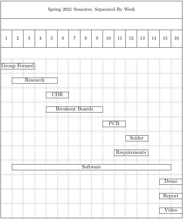
Schedule
Concept and Preliminary Design
Different solutions were originally proposed for the three main sensor subsystems before deciding on our chosen RFID, IMU, IR, LDC and wheel encoders. The sections below further explain our process for selection.
Literature Review
Provide theoretical background, concepts involved in the design process and a summary of the key literature and online resources (e.g. Arxterra – Project Summary Post) that has been researched and used in the design effort. A summary of similar previous designs can also be discussed to show strength and weakness of your design compared to others.
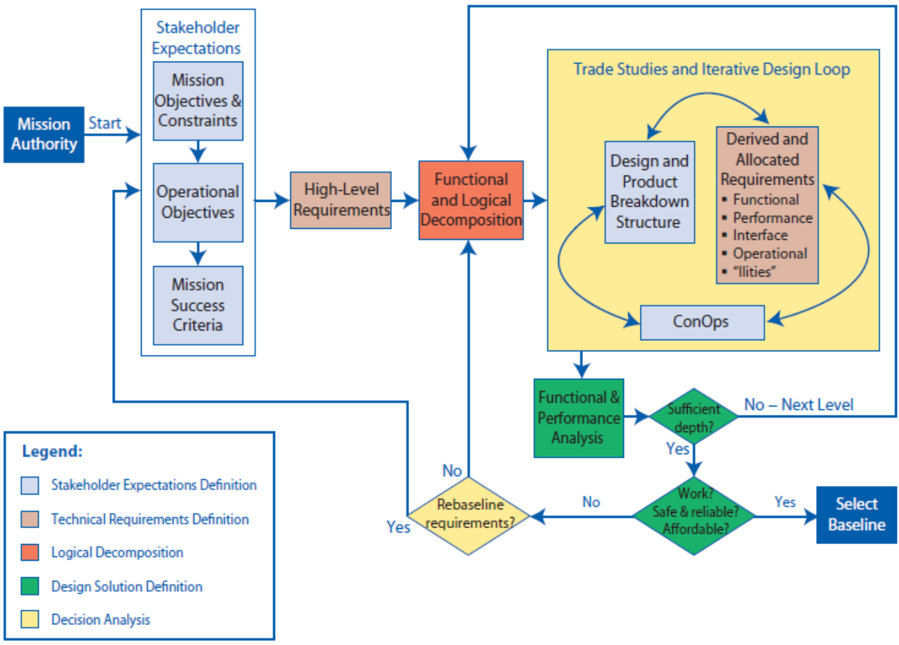
From the Arxterra lectures, the first steps of the design process are to understand the objectives from the clients/shareholders: notably their mission objectives, constrains, operational objectives, and mission success criteria.
To successfully meet their mission success criteria, research and iteration is required. The figure below illustrates the iterative nature of the design process.
A preliminary starting point is examining the existing literature on the desired mission objectives.
Our team researched existing models heavily. There are many different types of robotic systems today using a wide variety of techniques to accomplish complex tasks while remaining confined by boundaries. The entire document with more information can be found here.
Design Innovation
Card Reading
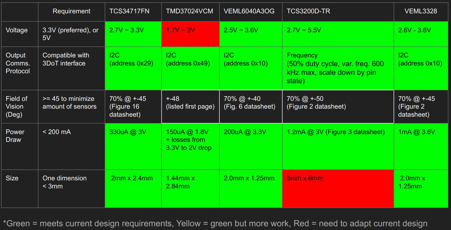
A color sensor was first proposed as a solution to card reading. The cards from the available set were analyzed and each of the classes of cards had their own color scheme. If a color sensor met the electrical requirements, the solution may be viable and would warrant further testing.
The size of the color sensor was constrained to less than 3 mm for space requirements; I measured four sensors would be needed to cover the entire range of the card at the height where the final circuit would be located. This led to an unexpected requirement; the color sensors were required to have at least four available I2C addresses so to alleviate the need for an additional multiplexor. From the guidance of Dr. Hill, I moved on to researching open-source RFID sensors.
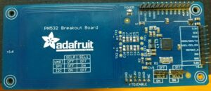
The PN532 from Adafruit caught my eye because of the tremendous amount of resources available on their website and on various GitHub pages. I purchased the breakout board and had it in my hands within two weeks.
I2C is set with external jumper pins and a software library is provided and filled with useful functions. Only six pins are needed: one for power, ground, SDA, SCK, and two digital interrupts.
Controls
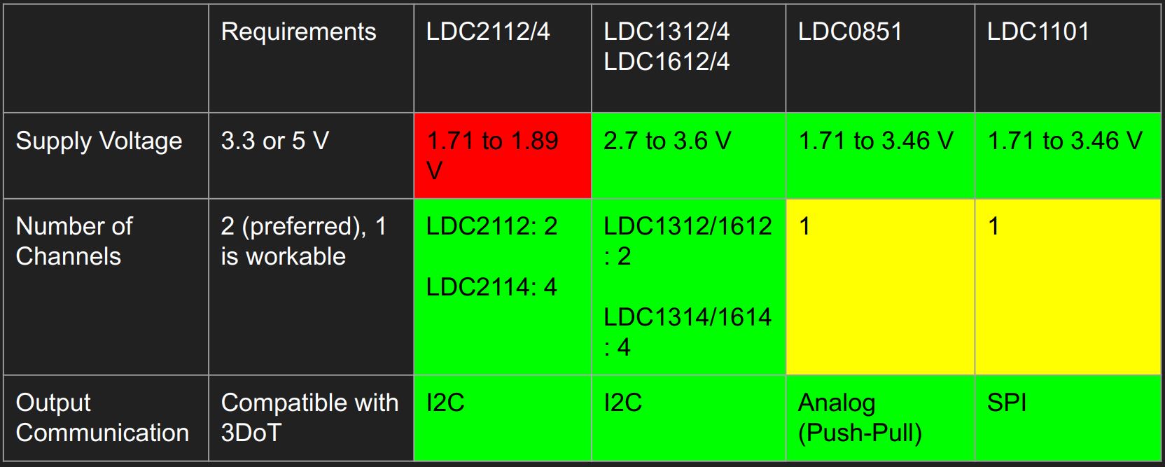
The plan for controls from the beginning was to use an IMU with a PID controller. A comparison of different IMU’s is presented below.
As more research was done, turning the robot came into question. After some discussion with Dr. Hill, a wheel encoder was determined to be a good fit for our purposes. Wheel encoders can precisely report the amount of rotations a wheel has undergone and use that data to understand the robot’s speed and travel distance.
Conceptual Design / Proposed Solution
| Card detection | RFID |
| Balancing | IMU |
| Turning | Wheel encoder |
| Room detection | IR sensors |
| Boundary detection | LDC |
Table 6: The final proposed solutions for HeroBot.
System Design / Final Design and Results
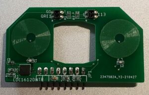
Our engineering team could not figure out how to detect rooms with our LDC, so the final design of HeroBot uses IR sensors for room detection and and an LDC for boundary detection.
In the same manner, we could not figure out how to turn using the IMU. After some research, wheel encoders seemed to be the best option and were added to the design.
System Block Diagram
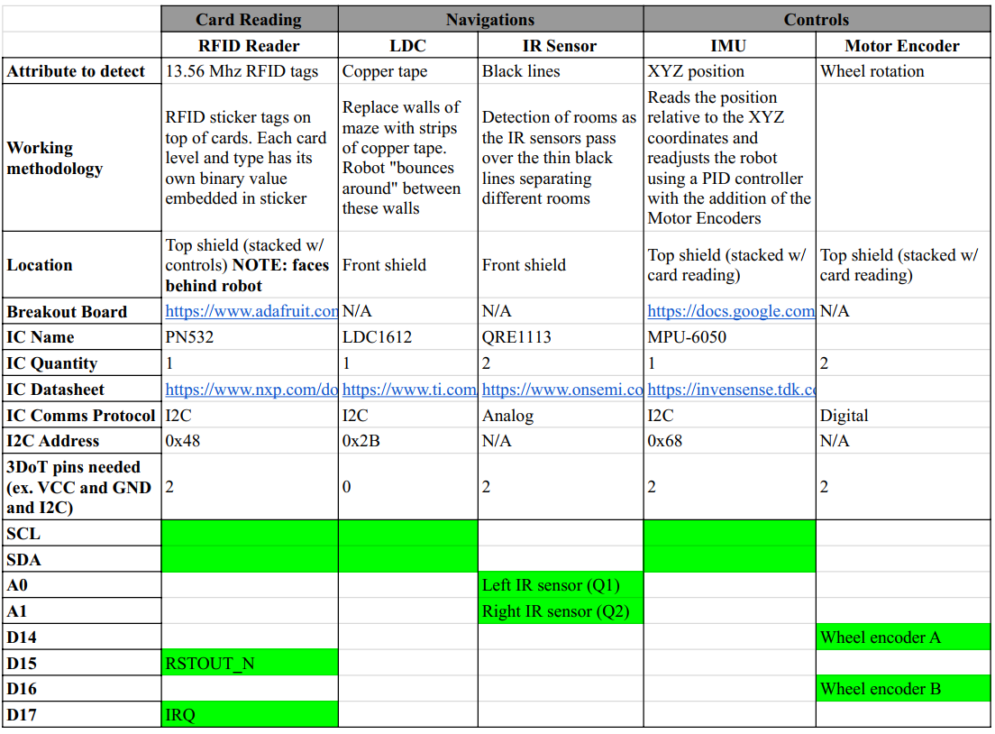
Hardware Interface Matrix
Electronic Design
Breakout boards were extensively used to prototype different solutions. The included resources on adafruit.com helped the card reading engineer to get his board up and running.
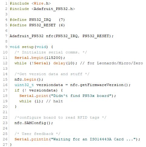
After wiring the pins to an Arduino, the open source files from Adafruit’s website were loaded in the Arduino IDE. The default settings were changed to match the I2C communications.
There are four parts to the setup for the RFID breakout board:
- Initialize the serial communications for the Arduino IDE
- Retrieve version data from the PN532 chip
- Configuring the breakout board with its input and output pins
- Give the user visual feedback that the program progressed successfully (or not)
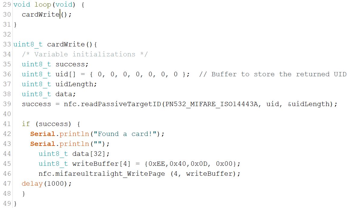
After playing around with the available software, a function provided in the examples to write to the card was adapted to fit the needs of the robot. This consisted mainly of simplifying the code; the result is shown in Figure 13.
The uid[] array contains the identification code unique to RFID tags. The length of this array is determined by the type of card; a standard 13.56Mhz card or an 13.56Mhz ultralight card (the ultralight tags are physically smaller and contains more than enough space to store data into). The function nfc.readPassiveTargetID() returns a boolean value based on the presence of an RFID card. The function writes a value of 0xEE400D00 on page 4 (pages 0 – 3 contain the identification info, page 4 is the available page to write data to) of the card.
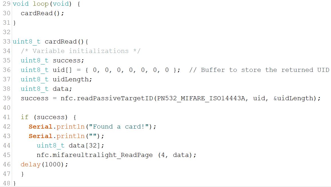
As with writing data to the card, a function was written to read the data from the card. The function works in a similar manner to the cardWrite() function.

Figure 15: The output of the RFID writer and reader on the serial monitor inside the Arduino IDE after running the write and then read function of Figure 13 and Figure 14.
The breakout board and the shown functions successfully detect the presence of a card and additionally can write and read unique data to and from it.
The software drivers for the Adafruit breakout board are presented below in the Firmware section.
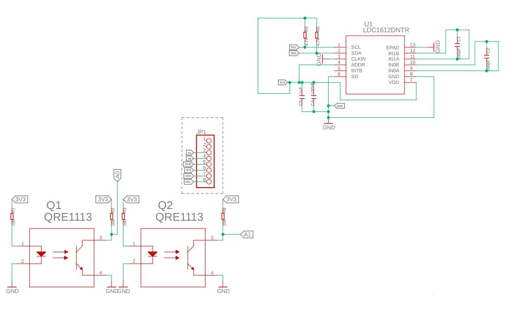
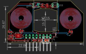
More details about prototyping with the LDC breakout board (as well as its PCB design) can be found within its blog post.
PCB Design
Card Reading
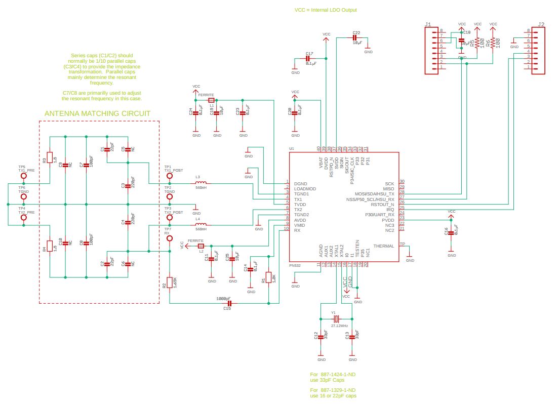
The data sheet for the PN532 specifies the operation of the chip. There were many alterations required to be compatible with the 3DoT.
To configure the chip to communicate via I2C, two pins need to set: pin 16 (SEL0) and pin 17 (SEL1) both must be pulled HIGH.
For interrupts and the ability to reset the chip in software, pin 25 (IRQ) and pin 26 (RSTOUT_N), respectively, must each be connected to a digital pin on the 3DoT.
Two 0.1 mm pitch 8×1 headers are used to connect the card reader to the top shield of the 3DoT. Of the 16 available pins only 6 are used:
- VCC (bulk decoupled with a 10uF capacitor)
- GND
- SDA (pulled up with a 100K resistor)
- SCL (pulled up with a 100K resistor)
- IRQ
- RSTOUT_N
After the layout was configured appropriately, the physical design began.
The PN532 manufacturer offers a design document describing their design process for custom antennas on the chip.
As antenna design is complex, it was determined by the card reading engineer that making minimal changes to the open source design was the best course of action.
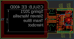
The first thing to do was to shape the board into the correct geometry. The RFID PCB is going to sit atop the top shield facing away from the robot (such that the card reader scans the room behind it). The Arxterra article titled “How to Make a SHield In Eagle CAD” was referred to for the dimensions needed to sit flush on top of the 3DoT headers.
The only physical location for the PCB was through the rear wooden chassis, so a notch would need to be cut from the chassis to accommodate the PCB.
Some passive components had to be moved aside to make room for the headers. Additionally, the decoupling capacitors are placed closer to their chip in this design than those in the original design.
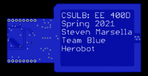
Custom text on the silkscreen layer was added to the bottom side to identify the board at a glance.
The PCB and its accompanying stencil was ordered through PCBWay. A blue color was arbitrarily chosen.
The fabricated PCB arrived in about a week from the order date. I tested for shorts immediately using continuity on a multimeter and nothing was shorted.
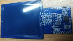
The figure below shows my attempt at soldering the board using a reflow hot plate purchased from Amazon. It was at this point I realized Mouser sent me the wrong ferrite beads and they were much too small for my applications. Instead, I used a small clipped lead from a resistor to short the pads the ferrite beads would have occupied.
Notice the large globs on the large black chip (the PN532) on the right side of the board. I could not solder the chip properly without shorting the pins.
Controls
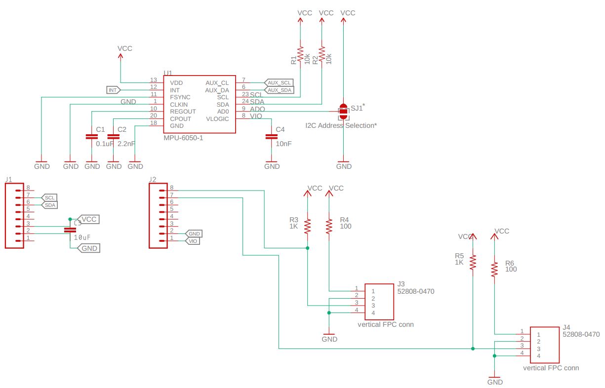
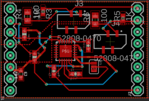
More details about designing the IMU can be found within its blog post.
Firmware
Card Reading
The RFID reader will scan for the presence of an RFID tag. To achieve this, a cardRead() function will be evoked which will simply return a TRUE or FALSE value.
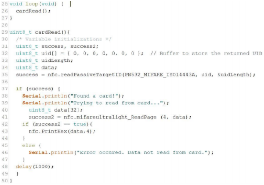
Figure 25: The software driver for reading an RFID tag. The function nfc.mifareultralight_ReadPage() is included with the PN532.h library and is used to read the specified page. This function is not necessary to determine the presence of a card, but is useful for determining whether data lies within a specific location in the RFID file-structure.
Controls
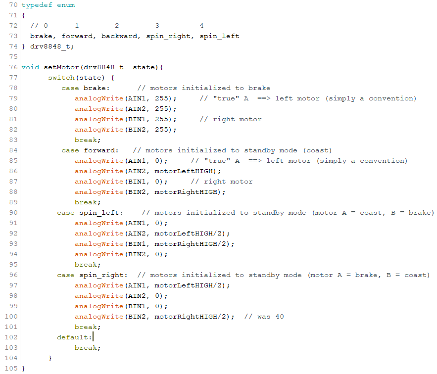
The motors have four possible states, shown in the table below.
| xIN1 | xIN1 | xOUT1 | xOUT2 | Result |
| 0 | 0 | Z | Z | Coast |
| 0 | 1 | L | H | Reverse |
| 1 | 0 | H | L | Forward |
| 1 | 1 | L | L | Brake |
Table 7: The logic table for the four states of the motors, found here.
With the above information, the turning function could be implemented by individually writing values to the motors, depending on our desired state.
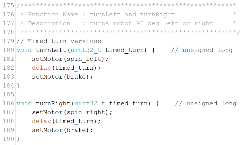
The setMotor() function is particularly useful when turning the motors, as seen in the figure below.
The above two turning functions accept a time as an input argument (in milliseconds) and will turn in the specified direction for as long as the input argument specified. The duration needed to turn left was experimentally determined on Steven’s robot to be about 420 milliseconds.
Information regarding the control division’s software drivers as they pertain to the IMU can be found in the software driver presentation.
The final version of HeroBot uses IR sensors for room and wall detection.
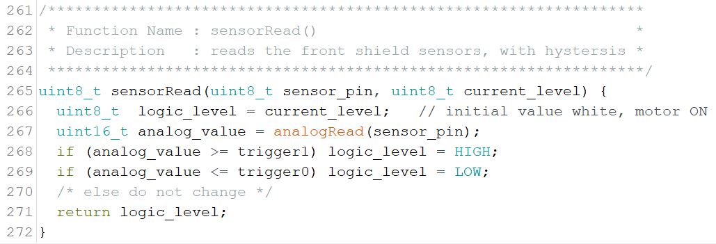
The first step was to understand the data coming in from the IR sensors using analogRead() when the sensors were over both white and black colors. For my robot, the values were about 300 over a black line and around 125 over a white area.
With this information, the function sensorRead() was created. This function reads the analog data received from the selected IR sensor and compares it to the predetermined thresholds of 125 and 300. If the analog values or greater than or equal to the high trigger or less than or equal to the low trigger , known as hysteresis, the function will return a new boolean number. If the analog value lies between the trigger values, the output value will not be changed.
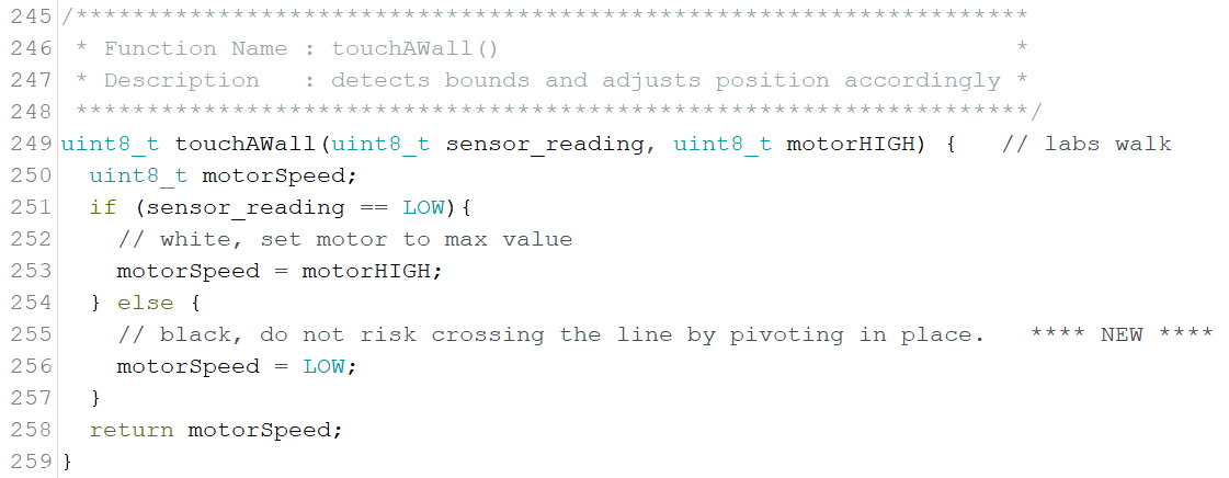
The touchAWall() function calls the sensorRead() (from the sensor_reading variable) to check the outer IR sensors. If HeroBot strays too far off the center of the path, an IR sensor will detect the black boundary line. motorHIGH is the adjusted PWM value at which the motor travels at a high speed. More information about these variables can be found in the code.
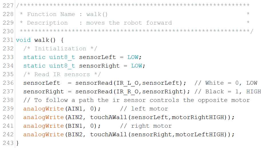
The walk() function moves HeroBot forward in a straight line. When an IR sensor touches a wall, this function slows down the appropriate motor to get the robot to straighten out and get back on the correct path. The motors are written to directly.
Information about the navigations division’s software drivers pertaining to the LDC can be found in this blog post.
Mission Software
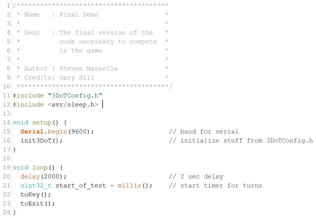
The main software program consists of a nested series of functions.
The 3DoTConfig.h software library included at the very top initialize the pins on the Atmega chip at the heart of the 3DoT and set them to either inputs and outputs. The
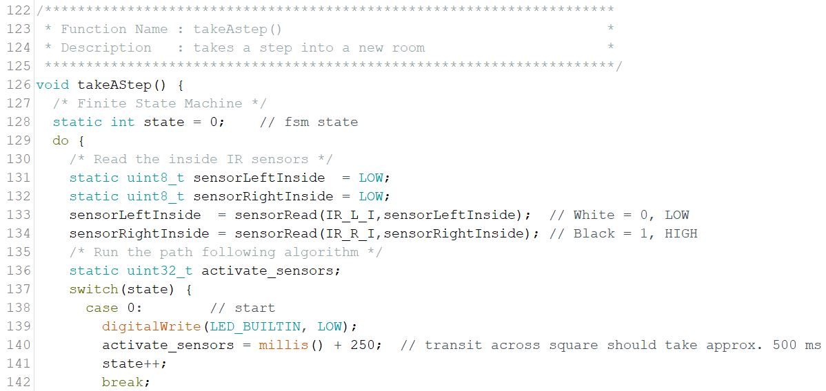
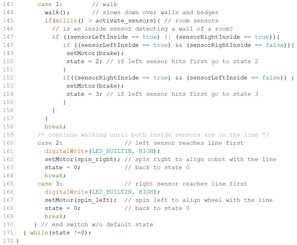
The takeAStep() function utilize a finite state machine to move the robot. It begins by checking the inner IR sensors to see if it has entered a new room. The software then enters state 0 of the switch case. In state 0, the built in LED is turned off and an offset is added to the timer corresponding to the amount of time it takes for the robot to pass through a room. The program then enters state 1 of the finite state machine.
In state 1, the walk() function is called to move the robot forward. If the amount of time that has passed is greater than the time it should take to pass through a room, the program will check the status of the inner IR sensors. If either of the IR sensors read a black line, the program will then check specifically which of the two it is. If the left IR sensor detects a black line and the right one doesn’t, the function proceeds to state 2 where the robot will rotate itself until both the IR sensors are on the black line. The same event occurs if the right IR sensor detects a black line and the left one doesn’t. This ensures the robot enters a new room straight every time.
Verification & Validation Test Plan
The strategy for verifying that the HeroBot design meets the design requirements laid out in the earlier sections of this document is a combination of source-code analysis, special tests, and visual inspections.
The overall validation for the design will be a live demonstration for the clients. The clients will decide if their mission objective has been met sufficiently.
To initially validate our design and related software, a minimum working example for a singular basic function is programmed, such as “walking” in a straight line and turning left and right.
Given a starting location, an exit location, and the location of the key card, HeroBot should be able to complete its objective.
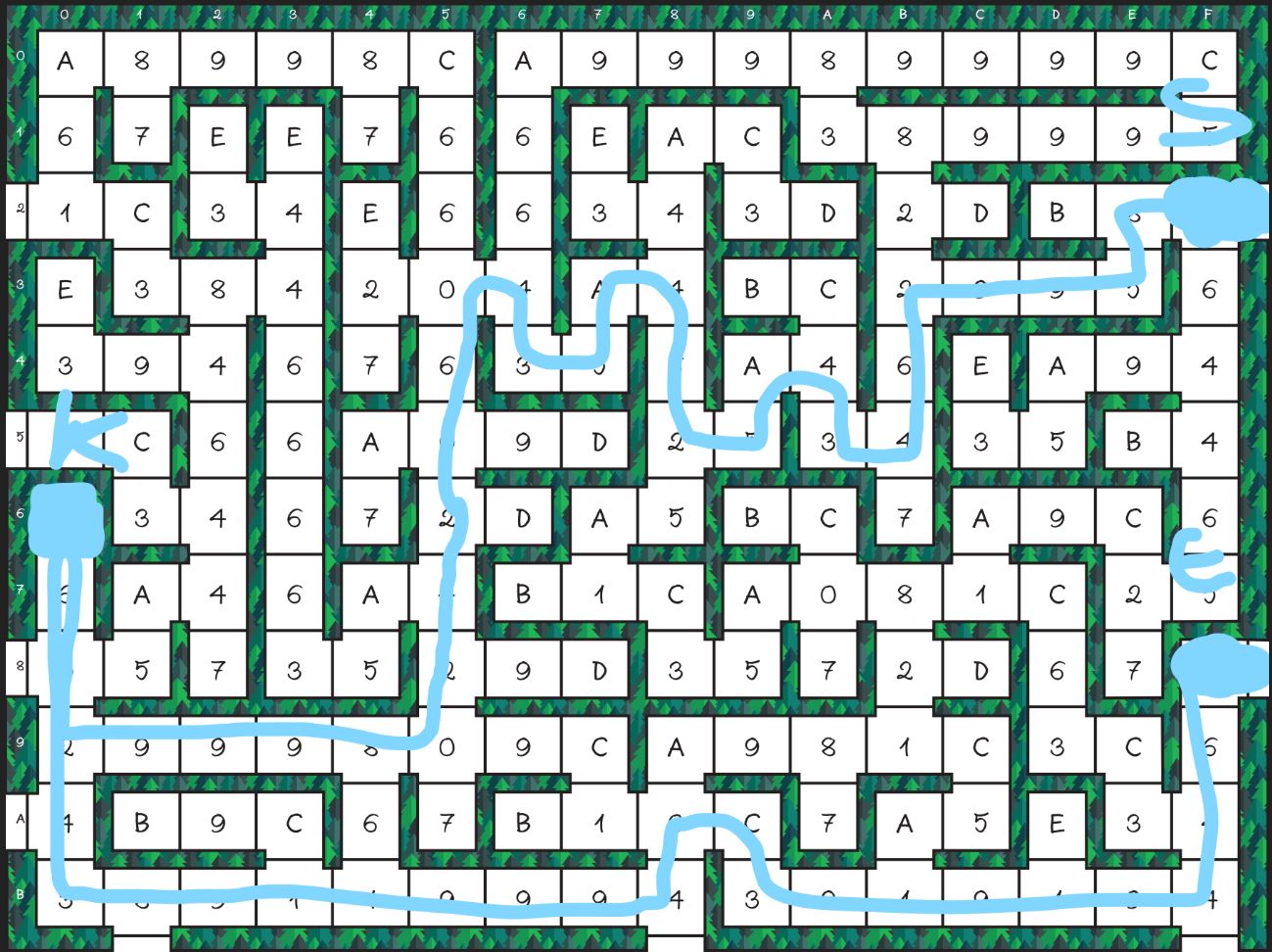
Figure 34: The path of the robot from its starting point to its designated exit through the location of the key card. “S” represents the starting square, “K” marks the key card, and “E” designates the exit square.
The complete verification matrix can be found here.
The video showing the robot completing the maze shown in Figure 34 can be found here.
The software by the Game Software Engineer can be found in its blog post.
Concluding Thoughts and Future Work
The final design of HeroBot was not the expected robot and there were many factors from which this lead.
We should have been in much more contact with TRC bosses and asked more questions during our design period. The HeroBot team would have greatly benefit from a stronger source of direction from its project manager.
Our online communications for different parts of the project between team members was not confined to specific areas. This lead to occasional confusion and the need to reiterate ideas many times and/or spend time searching for the necessary information. This became especially apparent when it was time to write this final blog post.
Our schedule was too relaxed; we were not acting with as much urgency as we should have been.
Many of our progress was at the final moments, before deadlines. For many assignments, we did not spend as much time as we should have and did not go through too many iterations.
For the future generations of HeroBot, the software should be changed such that a non-deterministic solution was used. The PCB design could also have been much neater.
References/Resources
These are the starting resource files for the next generation of robots. All documentation shall be uploaded, linked to, and archived in to the Arxterra Google Drive. The “Resource” section includes links to the following material.
- Project Video (the final shot of the robot solving the maze is 2x speed)
- CDR PowerPoint & PDF
- Schedule (Gantt chart)
- Verification and Validation Plan
- EagleCAD files (compressed)
- Arduino and/or C++ Code (compressed)
- Bill of materials (complete)
- Bill of materials (single robot)
- Spring 2019 Maze Metal Detector Sensor Design Fabrication
- Ilomilo Spring 2020 Metal Detection using the TI LDC0851
- TI LDC Sensor Design

