HM-11 Bluetooth Module Soldering
Written by Melwin Pakpahan (Missions, Systems, & Test)
Description
This post will cover the assembly of the HM-11 Bluetooth module onto the 3DoT board. This module allows Bluetooth communication between the Arxterra app on an Android phone and the 3DoT board.
Pinout
According to the 3DoT v5.03 schematic, the functional pins of the HM-11 module used for the 3DoT Board are:
- Pin 2: UART_TX
- Pin 4: UART_RX
- Pin 9: VCC
- Pin 12: GND
Figure One shows the schematic of the HM-11 module taken from the 3DoT v5.03 schematic.
Assembly
Assembly of the component is as follows:
- Component is placed onto the board.
- Flux is liberally applied to the pins, pads, and it surrounding areas.
- A technique called drag-soldering is applied to solder the module on.
- The tip of the soldering iron is tinned with an amount needed to cover all pins in a row.
- Then, the tip of the iron is dragged across that row of pins.
- Drag-soldering is repeated on the rest of the row of pins.
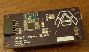
Finished assembly is shown in Figure Two.
Discussion
Pins 2, 4, 9, and 12 are the functional pins that must be soldered on to the board. In our case, all the pins are soldered onto the board to better hold the module in its place. However, this is not recommended because it makes the board more difficult to remove should there be any discrepancies. Therefore, only power (pin 9), ground (pin 12), transmit (pin 2), and receive (pin 4) should be soldered.
References
[1] HM-11 – Reference One
[2] 3DoT v5.03 Schematic – Reference Two
[3] Drag-soldering – Reference Three


