HoundBot Summary Blog Post
Author: Enrique Garnica
Verification:
Table of Contents
Mission Roles and Summary
- Game Software
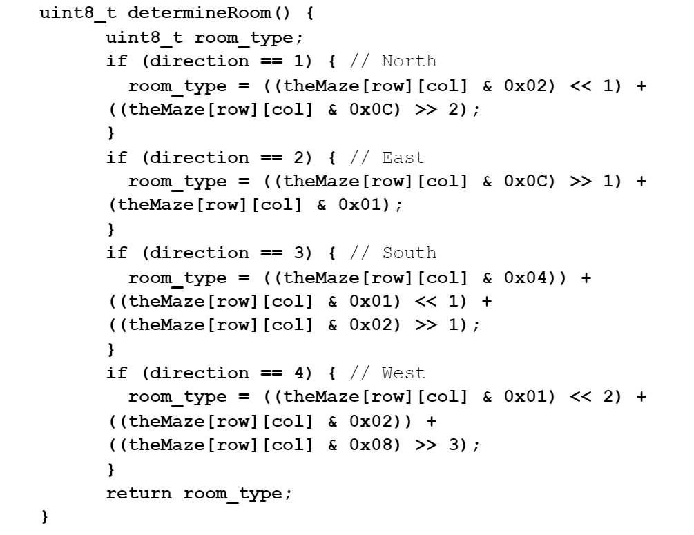
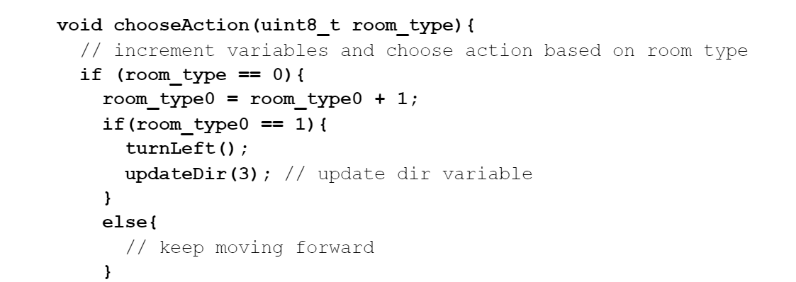
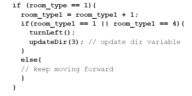
Arduino c++ code was written to find which actions the 3Dot robot would perform when entering a room, determining the room type until it finds the key and exits the maze as specified by the Game Master.
- Navigation
A front shield was designed for the 3DoT robot for the purposes of discerning when the robot enters a new room and preventing the robot from running over a wall. To accomplish this, the front shield was designed to detect both the walls and the edges of each room in the maze.
- Motor Controls
Hound Bot used the pre-issued DRV8848 Motor and Sparkfun 6050-MPU to turn the robot left, right and 180.
- Card Reading
A camera shield is designed for detecting the key card based on QR code that is placed on the card.
Requirements
All Level 1 and Level 2 requirements for this project can be found in the link below.
https://docs.google.com/document/d/1xH5mMfC42kO2pkrCyp-dNzPl51BB4-WO0vcETV-KT4A/edit?usp=sharing
Project Report
Cost
All expenses for the project are summarized in the following link to the parts list.
https://docs.google.com/spreadsheets/d/1ACAI3gHPG0gQ_OTKOqJs6ZjS6n74YiGNKz0duGscH4U/edit?usp=sharing
Schedule
The game software code was completed on time. The hardware, however, had several issues that prevented the project from being fully completed on time. The group was expected to have four working robots, each with a front shield and two top shields for navigation, controls, and card reading. By the time of the final, only one front shield was finished, and no top shields were finished.
Concept and Preliminary Design
- Game Software
Creating the code for this project required a few things: detecting the locations of every card in the maze, what pathways are available along with obstacles, and what the best pathway to take would be. A 2D array featured hex values representing every room in the maze. An algorithm would determine the optimal solution the robot could take, choosing one of the main four goals provided to us by the Game Master.
To find all the cards in the maze, multiple for loops were created, one for exits, monsters, treasures, and weapons. Monster, Weapon, and Treasure locating for loops scanned the entire maze, requiring the 2nd digit of a hex value to match its value. Exit locating for loops had the extra step of searching not just every row and column for any potential exits, but corners as well. From all this information, a structure was created to contain all relevant information found within the maze.
- Navigation
To accomplish the task of detecting walls and room borders using the front shield, several ideas were considered, including distance sensors, a camera, and RGB sensors. However, distance sensors would require the added difficulty of creating a physical maze. Furthermore, the camera was discarded as an option because the class required that each person in a group use different hardware, and the card reader had already decided to use a camera (see card reader section below). Therefore, RGB sensors were chosen as the best option for the front shield’s navigation role.
Several options for RGB sensors were then found and compared. Table 1 below shows the comparison of several key design considerations. The TCS34725 was chosen due to the fact that it had an open source design schematic that included an LED. The open source schematic saved time in later stages because it could be used as the basis for the front shield design.
| Parameter | Requirements | TCS34725 | ISL29125 | SEN0101 |
| Size | Width < 1.125’’
Length < 3’’ |
0.8’’ x 0.79’’ | 0.7’’ x 0.6’’ | 1.12’’ x 1.12’’ |
| Connection Type | Compatible with 3Dot Board | SDA and SCL (I2C) | SDA and SCL (I2C) | Digital Pin (Frequency change) |
| Measurement Speed | < 0.156 seconds | 2.5 us
(400 kHz Clock Frequency) |
2 us
(500 kHz Clock Frequency) |
< 0.5 seconds
(Min output frequency = 2 Hz) |
| Other Features | N/A | LED Installed | N/A | LED Installed |
Table 1: Comparison of Several Different RGB Sensors
Green = meets requirements
Yellow = Borderline of meeting requirements. May cause problems
Red = Does not meet requirements
Due to the fact that the chosen RGB sensor used an I2C connection and every RGB sensor would have the same I2C address, an I2C multiplexer was needed to connect every sensor simultaneously. Specifically, the TCA9548A multiplexer was chosen. Without the multiplexer, each sensor would need to be connected to a different set of I2C pins, which is impossible because the front sensor only has access to one set of I2C pins.
Figure 1 shows the preliminary design for the front shield. The shield was designed with three RGB sensors: one on the front, and one to each of the sides. The front sensor detects the front boundary of a room to tell the robot when it is entering a new room. The side sensors detect the left and right boundaries of the room the robot is in, and this information is used to keep it going in a straight line.
Figure 1: Front Shield Conceptual Design, Navigation
- Motor Controls
To help the robot turn, we considered using a gyro and accelerometer sensor. By using the yaw value provided by the gyro/accelerometer we could design a shield that could stack on top of the 3DoT board and determine the orientation of our robot. Then through software control how the robot would turn. Conventionally, the sensors in the following table communicated in I2C, which made it conventional to use with 3DoT board. Upon research, InvenSense MPU 6050, had a lot of resources and example code that helped us develop a top shield sooner.
| Requirements | SparkFun Triple Axis Accelerometer and Gyro Breakout – MPU-6050 | Grove – 3-Axis Digital Gyro | BNO055 9-DOF Absolute Orientation IMU |
| Voltage | 3-5V | 2.1V to 3.6V | 3 or 5 |
| Connection Type | I2C SDA/SCL Compatible with 3-DOT | I2C SDA/SCL | I2C |
| Size | 1 x 0.6 x 0.09″ (25.5 x 15.2 x 2.48mm) | 20mm x20mm x15mm | 20mm x20mm x15mm |
| Gyroscope | ±250, ±500, ±1000, and ±2000 Degrees Per Second
Measures rotations about the x,y, and z axis. The specification determines the maximum angular speeds 2000 being the highest. |
X-, Y-, and Z-Axis angular rate sensors:
±2000°/sec |
Three axis of orientation |
| Accelerometer Range | ±2g, ±4g, ±8g and ±16g
Detects angle of tilt or inclination along the X, Y and Z axes. This displacement of moving plate (mass) unbalances the differential capacitor which results in sensor output. The units of range are in gravitational units |
none | Three axis of acceleration |
| Price | $29.95 | $19.90 | $34.95 |
Table 2: Comparing different gyro/accelerometer sensors. Checking sensibility ranges for accuracy and prices.
- Card Reading
At first, to detect the card, two sensors such as RGB and camera are considered. Based on the research for identifying the card, a camera was an easier method for identifying the card. I came up with three different camera sensors (Pixy2, Husky Lense Gravity & Jevois A33), but not only none of them were completely hardware and software open-source but also they didn’t meet the requirement(T_capture<450 ms, Vcc<5, D_object<15 cm) of an acceptable camera sensor based on project’s need, then I found ''ESP32 with Camera Module OV2640'' which was an open-source camera (hardware & software) which also met the requirement(T_capture=100 ms, Vcc=3.3-5v, D_object=12 cm) . Besides, I found it more accurate to identify the images (image recognition) by processing the image. Also, scanning the QR code and color detecting were other reasons that could be done by this camera.
System Design/ Final Design and Results
- Game Software
Due to the descope of the mission objective, the code became simplified significantly. Originally, the code included scanning of the maze and locations of various cards (monsters, weapons & treasures) and creating an optimal solution. Instead, the new mission objective required finding a key before exiting the maze. We had to focus on a new element called Room Types. This would determine the actions the 3Dot would take upon entering each room in its path while traversing the maze.
- Navigation
The initial design had an I2C multiplexer on the top side of the shield. However, putting the shield together in Eagle showed that all three sensors and the multiplexer could all fit on the bottom side of the shield. Furthermore, a space was set aside on the shield to place a caster wheel so the robot could balance properly.
- Motor Controls
Since the top shield would also be used for the camera module additional jumpers were added to stack the Camera Shield. Moreover, unnecessary pins that would allow us to connect other IMUs were grounded as we would not use them for this project. Furthermore, we considered adding the wheel encoder, but with limited time we discarded the idea.
- Card Reading
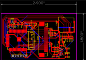
It tried to simplify the schematic of the ESP32 camera module by removing some parts such as the 5V regulator (since 3DOT supports 5V and 3.3 V), Flash LED and extra pins which were not necessary for the camera shield. Figure 2 shows the final design for the camera shield.
Figure 2: Camera sensor design
Results
- Game Software
The final design of the software was reduced significantly, featuring only the 2D array of all rooms, starting coordinates / values, and entirely new functions. Said functions would update the robot’s location, determining the room type, and what actions would be taken when the robot enters a room. Lastly, the need to scan the entire maze was removed due to its lack of necessity when we were able to create a path of our own that led to the key. Luckily, the robot was able to enter the maze, go through as we planned out for it, and take the necessary actions to maneuver through the maze until it found the key and the exit.
- Navigation
The final design had three pairs of TCS34725 RGB sensors, and each one had a Wurth 158302250 LED to provide reflected light for the sensors. Each RGB sensor’s I2C pins was connected to the inputs of a TCA9544APWR I2C multiplexer. The SDA and SCL pins of the multiplexer were connected to SDA and SCL on the 3DoT’s front pins.
The final design schematic, Eagle files, and finished PCB are shown in the “Electronic Design” section below. The front shield successfully allowed the robot to navigate the maze. A successful maze traversal can be seen in the project video, linked in the References at the end of this post.
- Motor Controls
The final design of the top shield, had the IMU X-axis facing the front of the robot to have better orientation and when calibrating the robot knew which way was forward. However, the design was not perfect and upon connection of the top shield the IMU was not detected.
The final design schematic, Eagle files, and finished PCB are shown in the “Electronic Design” section below.
- Card Reading
After placing the camera shield in the best position for identifying the card on the top of the robot, the QR code detected successfully. The final result of how to detect the card is shown in the video.
Modeling / Experimental Results
- Navigation
To test out the navigation front shield design, the Adafruit TCS34725 breakout board was tested to ensure that the sensors would work. The software was from AdaFruit.
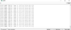
This link also has open source code that can be used to start reading the sensor. When the sensor is hooked up correctly with the open source code being used in Arduino, the serial monitor should show the sensor readings as shown in Figure 3. The sensor should give nonzero readings for R, G, B, and C, which represent red, green, blue, and clear, respectively.
Figure 3: RGB Sensor readings
- Motor Controls
The following was printed from the serial monitor:
It describes all values read by the IMU, since the IMU output data in angle values the values were converted into decimal for our convenience.
Figure 4: IMU Readings
To determine how much the robot needed to turn, we only needed yaw value, but wanted to see if any of the other values would affect our robot. Since our whole robot wasn’t implemented; in theory, whenever the robot turned it would use 0 as its reference point. Once achieved set point, the robot could continue coasting through the maze.
- Card Reading
To test the camera sensor for detecting the card, the code uploaded to the ESP 32 camera module and then show QR code to the camera which the result in the serial monitor as shown in the following figure.
Figure 5: QR code detection
Electronic Design
- Navigation
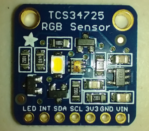
The progression of the Navigation front shield PCB design is as follows. First, the Adafruit TCS34725 breakout board was used as a base for the design, shown in Figure 6. The Eagle files for this breakout board can be found on the Adafruit website: https://www.adafruit.com/product/1334?gclid=CjwKCAjwnPOEBhA0EiwA609Recl25ermMdtifFclPRliZEaMPWy7bIYMqmFadlkDZFwjhmqf5pNM2RoCTC4QAvD_BwE
Figure 6: Adafruit TCS34725 breakout board
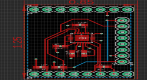
The sensor, LED, and 68 Ohm resistor on this board was then added to the custom PCB design. Every other part of the breakout board was unnecessary, including the 3.3 V Voltage regulator and the LED control. The pull-up resistors on the breakout board were not necessary because the I2C multiplexer would deal with those issues. Figure 7 shows the final front shield PCB design, and the Eagle file for the PCB can be found in the References at the end of the blog post.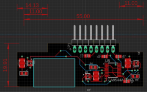
Figure 7: Navigation Front Shield Eagle Board Design
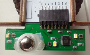
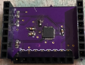
Finally, the finished product is shown in Figure 8. Due to issues with the PCB manufacturer, no space was removed for the caster wheel, so the caster was instead taped to the shield.
Figure 8: Finished Navigation Front Shield PCB
- Motor Controls
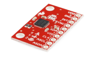
The initial design for the top shield came from the SPARKFUN-MPU6050. However, modifications were made to best meet our needs. For example, ASDA, ASCL, CLK, and SYNC were directly connected to ground as they would be unused pins and the datasheet suggested these pins be grounded if unused. Furthermore, VIO and ADO were connected to VDD, this was because without VIO the chip would also not function. ADO was set to high as well, as this controlled the I2C address and connecting it to high helped us with the PCB layout. Additionally, the IMU orientation was changed and set to face the front of the board.
Fig 9: Sparkfun IMU-6050
Moreover, an additional jumper was integrated into the top shield since our Card Reader stated camera module would sit at the front and connect to the top of the 3DoT board.
Fig 10: Top Shield IMU from Eagle Files. Located in Appendix as PCBDesign_2
Unfortunately, after continuity testing and connecting directly to the 3DoT board, our top shield PCB was not being recognized and we then presented the project with the SPARKFUN-6050 breakout board.
Fig 11: Finished PCB TOP Shield IMU
- Card Reading
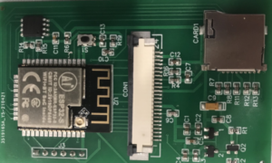
The PCB is designed in EagleCAD software. Finally, after getting design approval, the PCB is ordered through some companies such as JLCPCB, OSH Park etc. The following figure is my final PCB design that took me about 14 days to be done completely.
Fig 13: Finished card reading camera shield PCB
Verification & Validation Test Plan
In the link below is the Verification Matrix used to ensure the robot functions correctly.
https://docs.google.com/spreadsheets/d/1VF5uzQnJN_EG5u6ksuSQVmREaaEfbv5SiLDxkaXJbyE/edit?usp=sharing
Concluding Thoughts
For the navigation engineer, there were several areas that could have been improved. First, the custom PCB front shield did not have a hole for the caster wheel because the manufacturer ignored the milling layer of the Eagle schematic. By the time the PCB had arrived, there was no way to fix the issue, so it needed to be right on the first try. Second, the biggest barrier to the navigation portion of the project being finished was the PCB creation. As stated earlier in the blog post, only one of the four front shield PCBs was complete by the time of the final. This is because the PCBs failed to work during the soldering process. As a proposed solution, the best way to maximize the success rate of PCBs would be to start early enough to allow for two iterations of the physical PCB. If the first iteration fails, the problems with it can be analyzed, and a second version of the PCB can be designed and created. This solution is probably impractical due to the short length of the class, but PCB design is difficult for beginners to do right on the first try.
References & Resources
- PCB Schematic Files – https://drive.google.com/drive/folders/1-G292hlA5Zoo3mXmpZDpt3tkzWsx5QZ6?usp=sharing
- Verification Matrix – https://drive.google.com/file/d/1uMj18-U1Rd1sBb6ToQsA0T9sbLLs33nh/view?usp=sharing
- Lv1 and Lv2 Requirements – https://drive.google.com/file/d/1E5zcXX-x-I4EZQ8Sb-ecLhsekjrtoQMX/view?usp=sharing
- Project Video – https://youtu.be/QJq4ySYs_eY

