How to create the Interface Matrix
By: Joseph Cho (Mission, Systems, and Testing)
Verified By: Intiser Kabir (Project Manager)
Approved By: Miguel Garcia (Quality Assurance)
Table of Contents
Introduction
The interface matrix will be used by the MST engineer and the E&C Hardware engineer to allocate the pinouts of the main PCB. The main PCB should be where the central processing is done. The 3DoT Board is the main PCB containing the microcontroller (ATmega32u4). If you have all the components picked out for the robot, the interface process should be easy.
Researching for the Interface Matrix
In order to start interfacing, we need to know what parts are used in the robot and how those parts are connected. A system block diagram will be very helpful to keep you organized.
If I2C addressing will be used, look up the I2C address of those parts (link to Adafruit I2C Address). I2C addresses have to be looked up to make sure that the parts that are being used do not overlap with other parts of the I2C bus. If addresses are overlapped, it is like having two people talking back to you the same time. Avoid having I2C addresses overlapped. We can use an I2C expander to avoid overlapping I2C addresses. While you are making a list of components, find a datasheet for each one of them. The datasheet will be used to pinout the PCB shields.
Interface Matrix Template

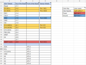
Figure 1: Interface Matrix Template
Description:
The 3DoT board has 16 available pins (2×8 pin) on the top of the board and 8 pins on the front of the board. You will start the interfacing by deciding how many pins will be utilized by the 3DoT Board. The interface matrix will be focusing on the leftmost column. Column B shows the pin names on top of the board, and Column C shows pin names on the front of the board. For the parts’ pin names, use the given pin name in the datasheet or schematic.
Examples
Description:
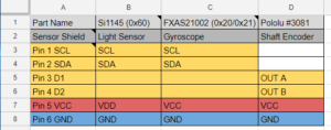
In this example, 6 pins have been utilized for the sensor shield. I have named and numbered those pins for easier reference in the future. The color codes can be decided on your own, but for this example, I have used yellow, red and blue. I have separated them this way because those pins have different uses. The color yellow is used for the data signals, red is for power, and blue is for ground.
Description:
Now that we have those 6 pins ready for use, connect them to the parts to the correct pins. As mentioned before, some parts may share the I2C pins (SCL and SDA) and this is totally fine unless their I2C addresses overlap. If that is the case, use an I2C expander to re-address the parts’ I2C addresses. The “Shaft Encoder” has two separate pins for the digital output, so they are connected to two separate digital pins on the shield. Note that the row is colored up to the column used. Since shaft encoder does not use pin 1 SCL and pin 2 SDA, they are not colored in.
Schematics of 3DoT board
Description:
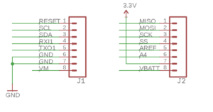
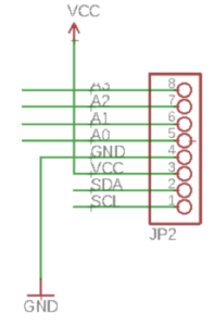
Schematics of the 3DoT board headers were added for reference. Look at the Arxterra website for more information about the 3DoT board.
Tips for future MST engineers:
- Make sure all the changes you make are approved by The Customer.
- Make sure both you and E&C Engineer know these interfaces and approve it. The E&C Hardware engineer will be using this interface matrix to create a custom PCB for your group.
- Communicate with your team members. Make sure that all your members know what parts are being used and how they are connected.
- Start with a breakout board for sensors. The custom PCB can be made like a sensor breakout board by the E&C hardware engineer. If the part you are trying to use is a breakout board, find the actual surface mounted microchip used for the sensing.
- Don’t mix up analog and digital pins. There are 5 analog pins (A0, A1, A2, A3, and A4) and I have made this mistake for not double checking. Check old blog posts, tutorials, and/or datasheets to make sure the pin being used is correctly connected.
Conclusion
Once the proper research is done for interfacing, the interface matrix is very simple to make. Read the notes in the examples and on the template for some parts skipped in this blog post. Lastly, double check your connections and get the matrix approved.
References
- https://docs.google.com/spreadsheets/d/1aarV8cXinkQM5X-mBR9ofC0-dlh1UwxvwzdLA5ykEEc/edit?usp=sharing
- https://learn.adafruit.com/i2c-addresses/the-list
- https://www.arxterra.com/3dot/
- https://docs.google.com/spreadsheets/d/1khUBCWJKz3PyFoB2Xp1CngnZKynNM2OerlcSHGMgjUc/edit?usp=sharing
- https://www.arxterra.com/at-st_interface_matrix/


